

Signalling Lamps
©RN Communications Branch Museum/Library
Clicking on an image will enlarge it. The enlarged image will open up as a pdf file in order for you to use the tools to enlarge the image even further.
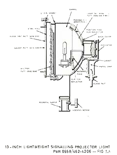
20 inch Signalling Projector Light
The lamp is fully automatic and will burn steadily at all angles of elevation and maintain its focus for approximately 50 minutes (the life of a pair of carbon filiments). When in correct focus the lamp will give a beam of 2.6 degrees divergence and maximum candle power of 45 million. For signalling purposes the lamp can be moved 0.4 inches nearer the mirror and will then give a beam of 4.5 degrees divergence and about 10 million candle power. The ventilation of the projector is provided by an exhaust fan mounted at the top of the barrel. A rectangular steel duct arranged about three inches above the arc, and connected to the suction side of the fan, removes the fumes from the barrel. The reflector is cooled by means of a fish-tail nozzle at the bottom of the barrel, the lower part of this nozzle being open to the atomosphere. The lamp is approximately in the correct focal position when the engraved line on its baser co-incides with the engraving marked "F" on the lamp runner of the projector. In this position the positive crater (forward end) should be at the focus of the mirror, from the front surface of the reflector. This should be checked by using a steel distance rod exactly equal in length to the crater distance. This steel rod should be kept on or nerar the projector. When signalling the rear door of the projector should normally be left with the position marked top uppermost, but this door can be rotated until the most comfortable position for hand grip and shoulder rest has been obtained. The operating handle is capable of adjustment in three different positions to sit individual signalman. The shutter should be operated gently by means of light pressure of the fingers. Any strong pressure on the operating handle produces noise and may cause damage to the mechanism.
15 inch Dual Purpose Signalling Projector
The 15 inch Dual Purpose Signalling Projector is designed for use either as a hand operated signalling projector or as a utility searchlight. It will replace the 10 inch Signalling Projector and the 20 inch Combined Searchlight and Projector. In this equipment a quartz iodide lamp is used instead of a carbon arc as the source of light, thereby achieving greater reliability with reduced maintenance. The projector can be operated at either of two power levels. For signallin gat normal ranges the lamp power is a nominal 400 Watts with a lamp life of approximately 100 hours. When the signalling range or weather conditions require it, or when the projector is being used for search purposes, a boost switch enables the lamp power to be increased to 800 wattes. Int his operating mode the life of the lamp is drastically reduced. Should the operational lamp fail for any reason, an alternative lamp fitted in the projector can be brough into action simply and rapidly by means of a change over handle. The projector is mounted on the standard spigot used for 10 inch signalling projectors.
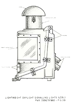
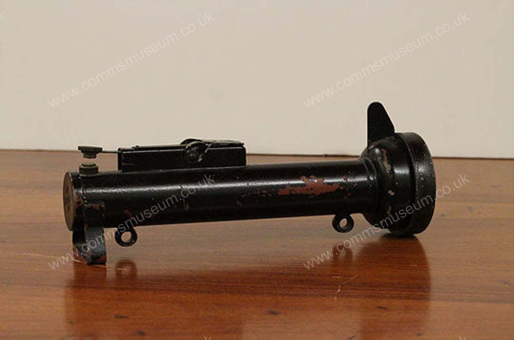
!0 inch Signalling Projector and 10 inch Lightweight Signalling Projector
In the 10 inch Signalling Projector the barrel is mounted in U-shaped tubular support arms which are fitted with a handle on each side for lifting purposes, and the design of the pedestal and barrel affords a high degree of accuracy of training and ease of manipulation. The signalling shutter is incorporated inside the front of the barrel and a front ring secures the glass in position outside the shutter. The glass reflector is fitted centrally in the back cover. The lamp when in focus has adispersion of 6 degrees giving a peak candle power of one million. A range of ten miles in bright sunlight with good weather may be expect in home waters.
The 10 inch light weight 10 inch Signalling Projector was introduced into service for coastal craft, inshore minesweepers, auxilliary minesweepers Type B, seaward defence craft, fast patrol boats and other small craft as may be approved. It is designed for 24 volt supply and has been modified for Tungsten Halogen 24V/250W lamps.
5 inch Hand Signal Light - Aldis
This is a modified Aldis which incorporates a watertight switch in the handle and is primarily for use in submarines and small craft where a more weatherproof light is required.
<These signal lights give a peak candle power of 150,000 with a divergence of 6 degrees. A range of 5 miles in bright sunlight in good weather may be expected in home waters.
The pistol grip is fitted with two triggers. The lower trigger is the switch handle which, when pressed, energises the lamp. This trigger should always be kept pressed when signalling. The upper trigger actuates the cylindrical signalling shutter.
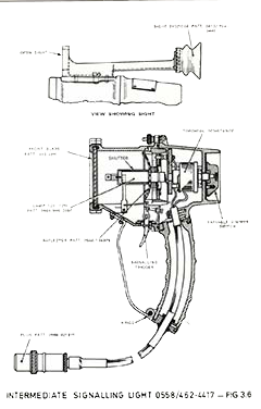
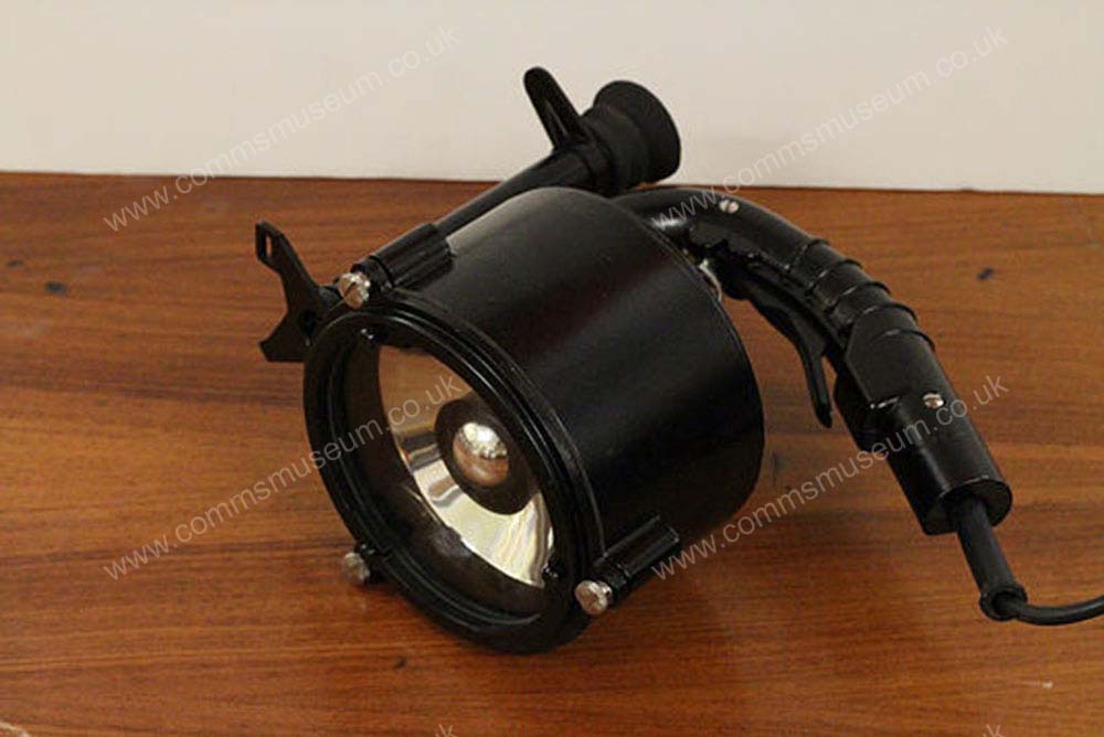
Intermediate Signal Light
The Intermediate Signal Light has the handle attached to both the front and rear portion of the body and it hinged at the bottom end of the handle. It has a dispersion of 10 degrees when using a pre-focus type lamp of 12V, 12W.
The candle power of the beam can range from 2 to 2,000 and can be varied by means of a regulating switch fitted on the back of the lantern. The signal light is operated by a trigger key in the handle which works a cylindrical shutter covering the lamp and it can be a 12 unspillable battery.
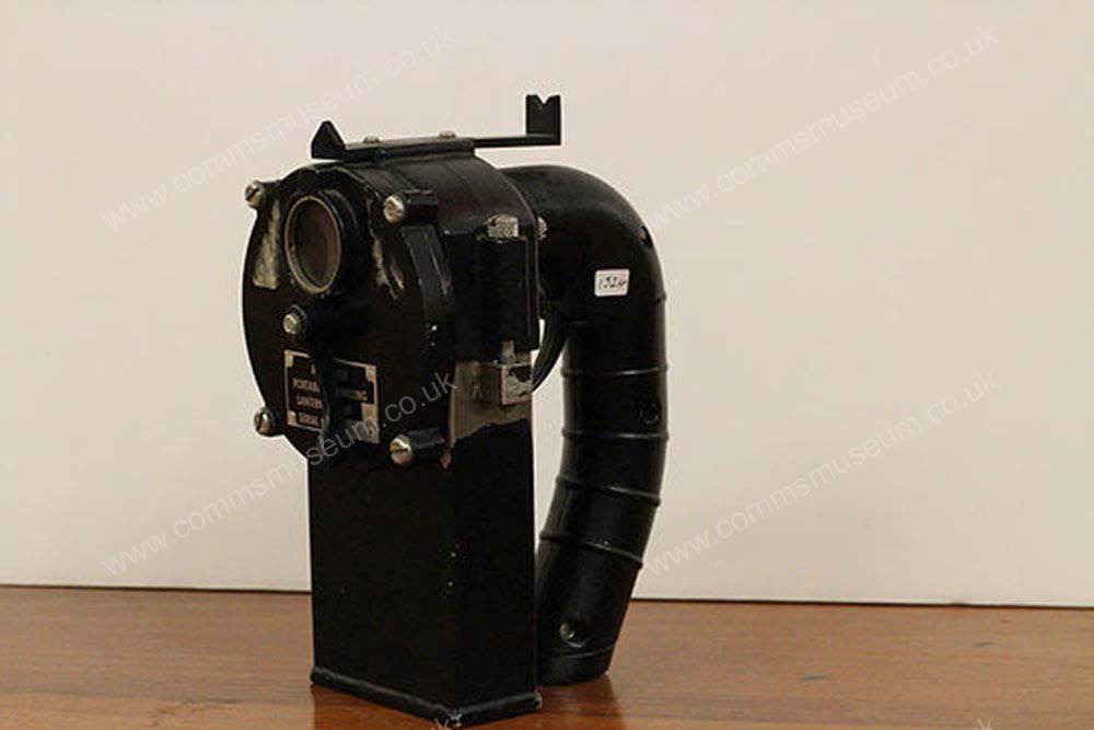
Battery Operated Portable Signal Light
These signal lights are designed for inter-ship communication between light craft in peace and war; and making special coloured signals requried during night torpedo attacks.
The signal lights are constructed in two separate portions; the lower on containing the battery, the upper on containing the lamp and the actuating mechanism. The battery is thus kept clear of the mechanism, the electrical connections being made through rustless steel spring plungers. The signal light uses a 2.5 volts, 0.75 amps and can house a spare lamp in the handle.
A rotating shutter is secured in friont and is fitted with four glass shades, namelyl; clear, neutral, red and green. Any of these shades can be brought in fron of the lamp by rotating the shutter. They are held in position by a spring click device. The approximate working ranges are one mile with the clear glass and half a mile with the remainder. The dispersion is approximately 18 degrees.