 |
AERIALSWritten by Godfrey Dykes© RN Communications Branch Museum/Library |
 |
TYPE |
|
|||
|---|---|---|---|---|
AWF |
A permanent fixed transmitting whip aerial fitted in many surface units. It operates in the HF band with a maximum efficiency in the region of 7MHz and with medium powered transmitters - up to 1kW. The aerial rod consists of four tapered steel rods screwed together to form a length of 35 ft. With light weight rods it becomes AWF(M). It is mounted on a base tuner, the ETA. The aerials are usually sited in the after part of the ship or well away from the receiving whip aerials. Connected directly to associated transmitter in non-ICS ships and through the EY Exchange on ICS ships.* * * * * * |
|||
AWN |
This is an entirely lightweight monopole whip aerial outfit designed primarily for use with common aerial working (CAW) for receivers. Four tubes, when assembled together, form a 30 ft whip aerial of 2� inches outside diameter at base and tapering to 1 inch diameter at top. It is mounted on a Group 'OA' deck insulator and fitted forward in the ship (including on top of the main gun) and away from the ship's transmitter aerials.For further details of Aerials AWN, AWO, AWQ and Aerials AWA to AWN* * * * * * |
|||
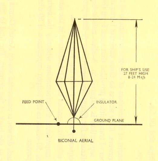
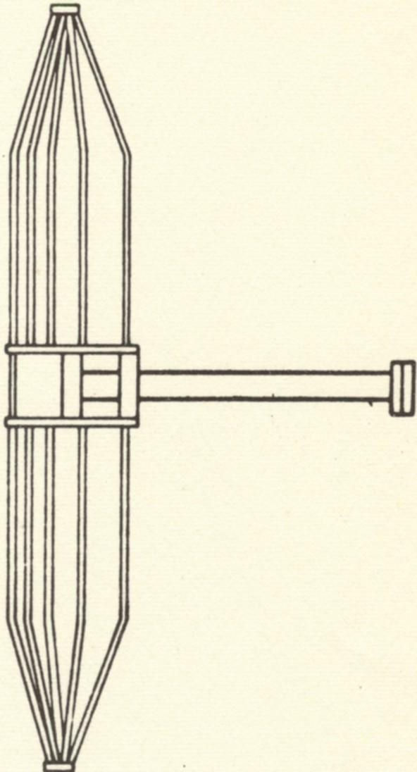
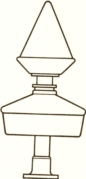
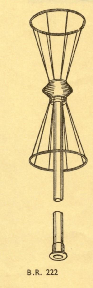
AGG |
A bi-conical aerial, fitted in large ships, when suitable ships superstructure is not available, used as a broadband transmitting aerial in the frequency range of 8 to 24 MHz with an RF power level of up to 1kW. The AGG is 28 feet tall and is 9 feet in diameter.For further details of AGG
|
|||
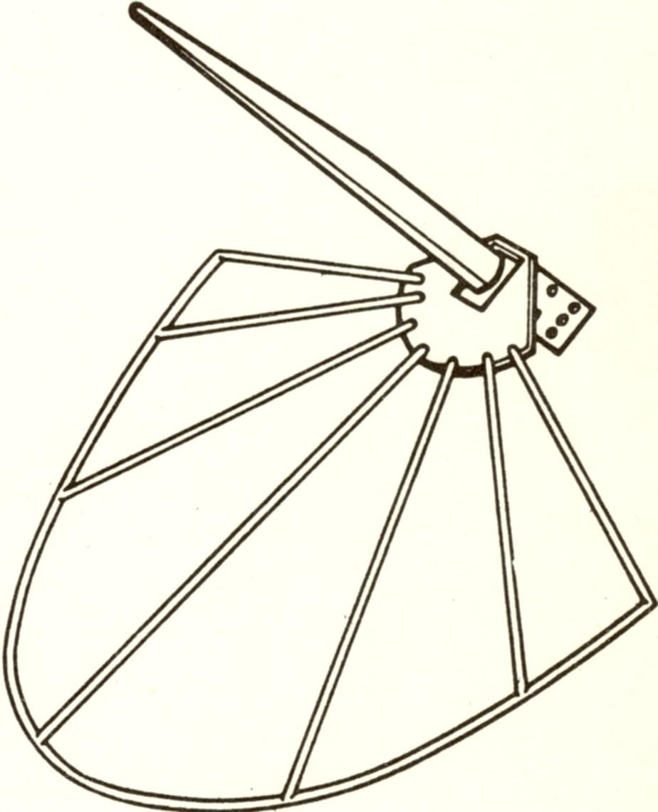
ACH |
VHF (27 to 100 MHz) aerial for mounting on a mast yard arm or a spur. A ground-plane quarter wave monopole mounted to accept both vertically and horizontally polarised radiations. Associated with the search receiver QR.For further details of ACH |
|||
AGT |
VHF (100 to 156 MHz) aerial for mounting on a 78 ft tall mast ashore. A ground plane quarter wave monopole. Used for 86/87 fitted in Royal Naval Air Stations.For further details of AGT |
|||
AJD |
VHF (100 to 156 MHz) aerial for mounting in groups of four on yard arms or spurs. For vertically polarised radiation. Equates with types AGR/AGS which are used on shore. Broadband half wave dipole.For further details of AJD |
|||
AJE(5) |
A UHF (225 to 400 MHz) aerial suitable for ship or shore application and for direct connection to unbalanced feeders. A broadband quarter wave monopole normally fitted for vertical polarised radiation both transmission and reception. When fitted on a ship, it is sited as shown in the jpeg on the top of the yard arm and upside down on the bottom of the yard arm. Thus a typical mast has four AJE's fitted, two to port and two to starboard.For further details of AJE |
|||
APH (AJA, AOH, ARU) |
VHF (100 to 144 MHz) aerial suitable for mounting on a yard arm or spur. APH(1) is for surface units and APH(2) - non-ferromagnetic version - for surface MCMV units. A simple half-wave dipole containing a built-in balancing unit of the parallel tube type. When the APH was fitted in small craft it became a AJA; when in a FF, DD or CC a AOH, and in a RR, an ARU. All associated with equipments 86M, 87M/P/Q, 689, and receiver CDV. |
|||
AQA |
VHF (130 to 210 MHz) aerial normally mounted on masts to accept vertically and horizontally polarised radiations. Associated with the search receiver QS. A broadband half wave dipole.
 |
|||
AWQ |
Designed to replace type AWH in small surface craft where the distance between transmitter and aerial does not exceed 20 feet. A thin light weight whip aerial used for either transmission or reception or both (via a S/R switch relay) for low powered HF transmission. The associated transmitter (and receiver if fed from S/R relay) on a frigate and above was known as "the emergency TX/RX". Approx 30 foot in length. |
|||
AYC |
A fixed SHF D/F aerial outfit in surface vessels in conjunction with AYD and AYE for use with radio search and D/F outfits UA2/3. 2500 to 4100 MHz. Horizontal and vertical polarisations.
|
|||
AYD |
A fixed SHF D/F aerial outfit in surface vessels in conjunction with AYC and AYE for use with radio search and D/F outfits UA2/3. 4100 to 7000 MHz. Horizontal and vertical polarisations.
|
|||
AYE |
A fixed SHF D/F aerial outfit in surface vessels in conjunction with AYC and AYD for use with radio search and D/F outfits UA2/3. 7000 to 11500 MHz. Horizontal and vertical polarisations.
|
|||
EAL |
Common aerial working (CAW) enables six or more HF and MF receivers to be worked from a common wire or whip aerial over the frequency range of 15kHz to 30MHz. The associated receivers are CAY (B40) and CAZ (B41). Associated aerial are AWN whips and wire aerial with Group OA DI's. 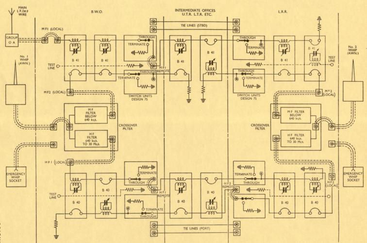 |
|||
EAM |
Common aerial working (CAW) enables up to nine HF transmitters to work into any one of three aerials over the frequency range of 2 to 24 MHz.The outfit is only fitted in cruisers and above.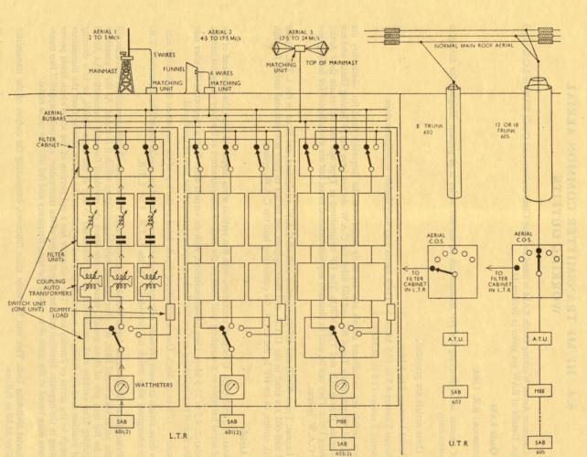 |
|||
EAO(4) |
Common aerial working (CAW) provides the receiver aerial and common aerial line distribution required for a number of receiver/transmitter outfits type CJM/641 and VLF/LF/MF to HF frequency converter FTA(1) as used in the ICS 2 Mixed Fit, or Reduced ICS2 fit. The CAW is suitable for ships with limited receiver communication requirement such as RFA's and Trial ships.
 |
|||
EAT(1) |
Distribution of radio signals from a single aerial to a large number of private broadcast receivers. Outfit EAT(1) can accommodate up to 400 receivers.
 |
|||
EAT(2) |
Distribution of radio signals from a single aerial to a large number of private broadcast receivers. Outfit EAT(2) can accommodate up to 40 receivers.
 |
|||
EAW (1), (2) and (3), (ICS1) |
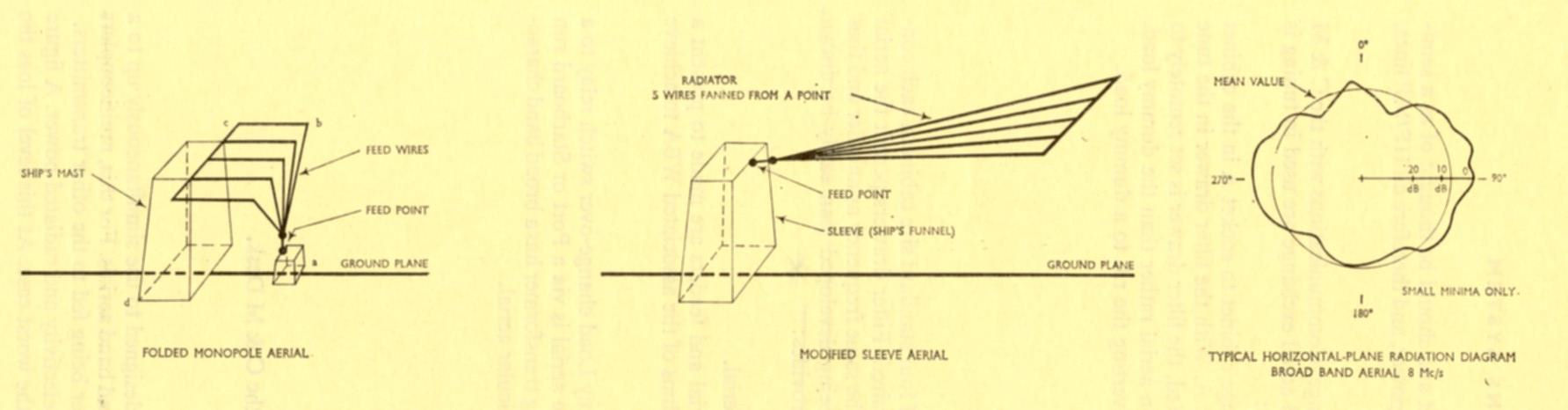
Common aerial working (CAW) enables a number of the transmitters in an ICS ship to work into any one of a number of aerials provided to cover the frequency range 2 to 24 MHz. The ships superstructure may be used to provide aerial equivalent to the FOLDED MONOPOLE or SLEEVE TYPE; alternatively, bi-conical aerials AGG or whip aerials AWF(M) may be fitted.
 |
|||
EAW (4), (5), (6) AND (7) and (ICS2) |
Common aerial working (CAW) enables up to eight ICS2 transmitters to radiate simultaneously from any one of a number of broadband aerials utilising the ships superstructure in the frequency range of 2 to 24 MHz with a minimum of degradation to the individual transmitter outputs. HF Filters fitted to cabinet are 2-6 MHz, 3-11.5MHz and 8-24MHZ and the suffix number after EAW (on left) dictates how many of each filters are fitted.
 |
|||
EAZ |
Common aerial working (CAW) enables up to eight receivers with low impedance inputs to be fed from a common high impedance wire aerial without reducing receiver performance. Range 2 to 27 MHz. Associated aerial is a high impedance wire aerial.
 |
|||
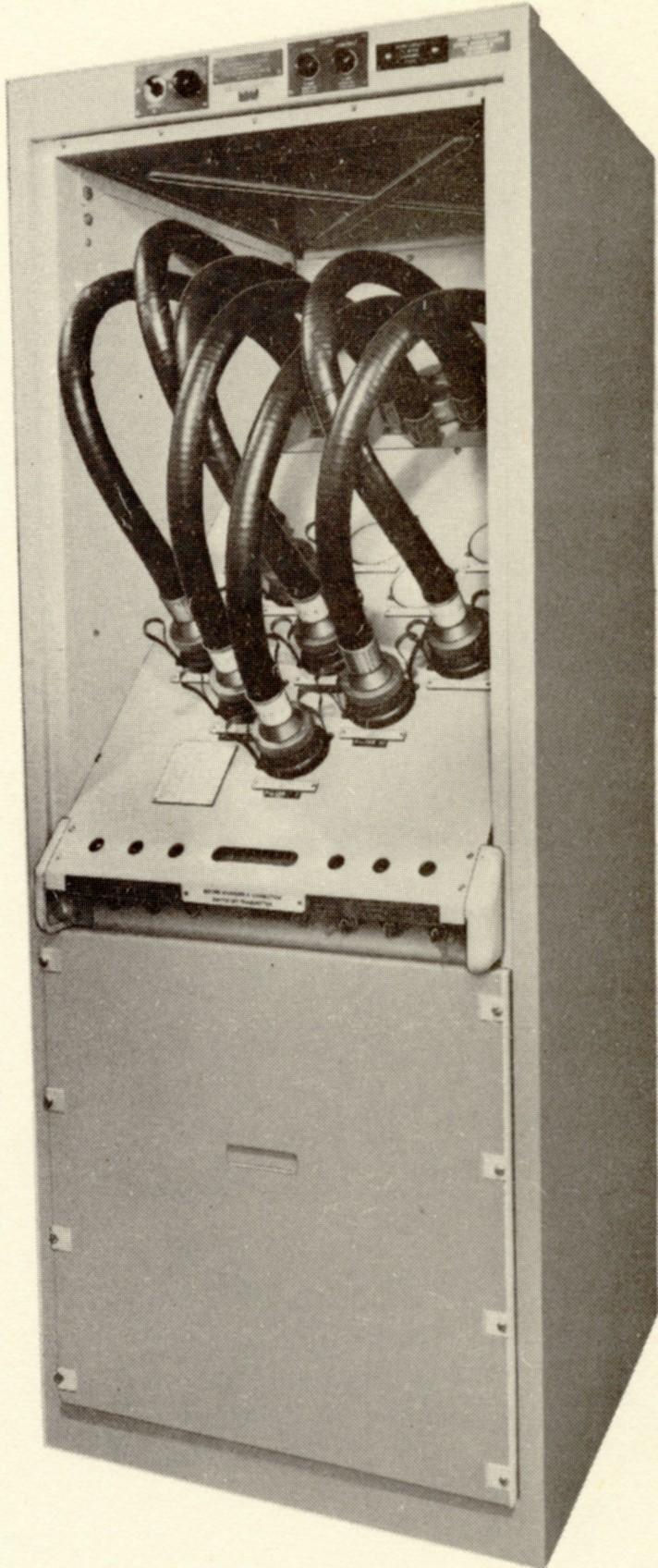
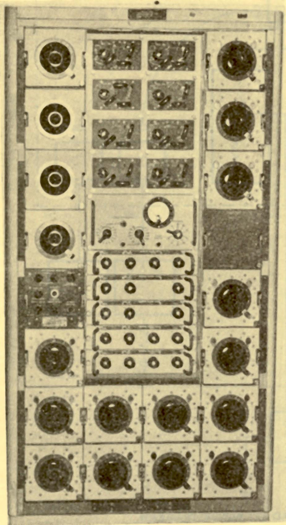
EY (1) - ICS 1 |
Outfit EY(1) fitted in conjunction with a common aerial outfit (CAW) and base tuning outfits enables the outputs of fourteen single-drive transmitters each supplied to a plug of the (transmitter) aerial exchange, to be connected to the aerial supplied from the sockets of the exchange. When fitted for triple-drive, eight transmitter inputs provide fourteen transmitter channels. Provision is made for the connection of six aerials A1-A6:- A1,2 and 3 Up to eight transmitters connected simultaneously via tuneable filters to each aerials ---transmitters connected to aerial filter sockets may alternatively be connected to one of the two external dummy loads --- A4 and 5 One transmitter connected to each of the base tuned HF whip aerials---A6 One transmitter connected to the MF base tuned wire aerial.
 |
|||
EY (2) - ICS 1 |
Outfit EY(1) fitted in conjunction with a common aerial outfit (CAW) and base tuning outfits enables the outputs of seven single-drive transmitters each supplied to a plug of the (transmitter) aerial exchange, to be connected to the aerial supplied from the sockets of the exchange. When fitted for triple-drive, four transmitter inputs provide seven transmitter channels. Provision is made for the connection of six aerials A1-A6:- A1 Up to six transmitters connected simultaneously via tuneable filters to the aerial ---transmitters connected to aerial filter sockets may alternatively be connected to one of the two external dummy loads --- A2,3,4 and 5 One transmitter connected to each of the base tuned HF whip aerials---A6 One transmitter connected to the MF base tuned wire aerial.
 |
|||
EY (2), (4) and (5) ICS 2 |
The exchange provides limited system flexibility whilst acting as a manual and relay controlled interface. The suffix variants relate to "tied" transmitters to specific aerials. (2) for example has no tied lines, whilst (5) has five transmitters tided to broadband aerials through EAW and one transmitter tied to a base tuned whip aerial.
 |
|||
EZ (4) |
The (receiver) aerial exchange outfit EZ(4) provides from a minimum of aerials a selection of aerial facilities to all LF/MF/HF receivers. The outfit is for use in frigates and above where ICS reception is fitted (ICS proper and COMIST ships (640/CJA)) which in the latter case, included B40's and B41's also.
 |
|||
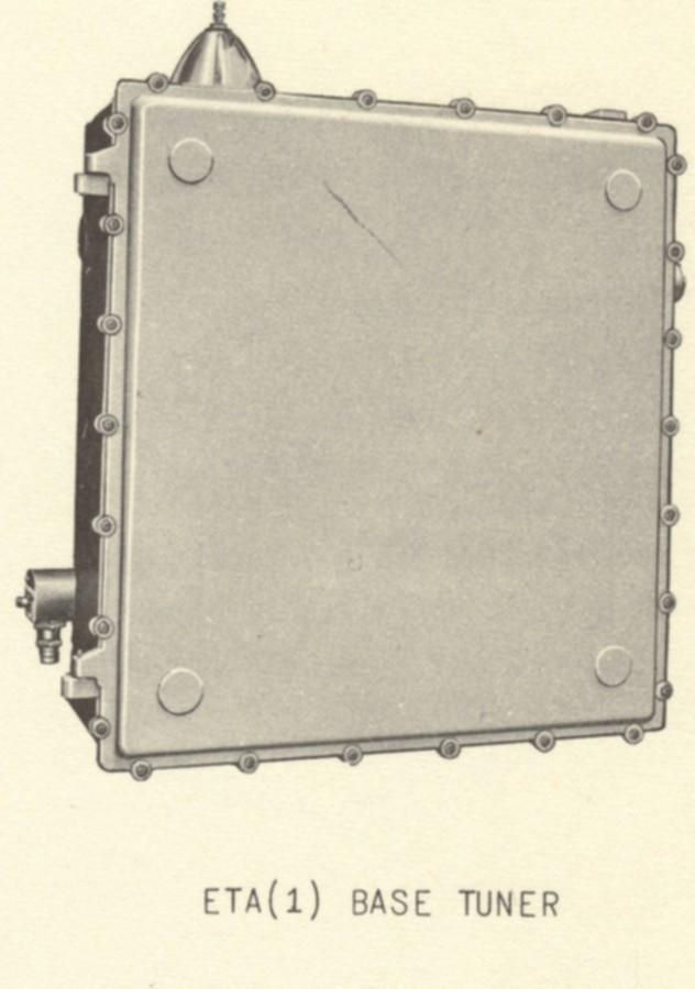
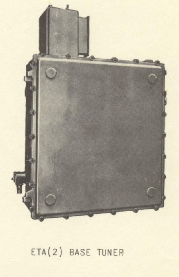
ETA 1 and 2 |
ETA's are base tuners capable of dissipating 800 watts, accepting an input of 1kW PEP between 1.5 and 24 MHz, with limitations caused by the frequency employed and emission type radiated. The ETA(1) is fitted in surface units frigates and above, and the ETA(2) is fitted in submarines. The (1) employs the AWF or AWF(M) aerials whilst the (2) employs the ALN/AWJ.
   |
|||
ETB |
The ETB is a base tuner used in ICS fits and 640 fitted ships to enable a wire aerial, which has a capacity greater than 240 pF and is quarter wave resonant above 3MHz, to be matched to a feeder cable of 50 ohms impedance using a remote control system. Between 1.5 and 3MHz the ETB will accept an input of 1kW PEP, but below 1.5MHz the input is limited to 500w PEP.
 |
|||
ETC |
This is a base tuned device and provides a means of matching various aerial impedances to a 50 ohm transmitter output ( e.g., transmitter type 640) over a frequency range of 1.5 to 24 MHz. Below 4MHz there are power limitations depending upon emission, but above 4MHz all emission can be 1kW.
 |
|||
ETD |
Provides a matched coupling between transmitters types 618 and 619 and whip aerial outfit AWH(M) or AWQ. 1.6 to 24 MHz. 100 watts PEP.
 |
|||
AJH |
Ship sited aerial associated with telemetry transmitted from the sender fitted in a Seaslug Guided Missile. Connected to outfit MBA.
 |
|||
AJC |
UHF aerial 225-400 MHz. Does exactly the same job as the AJE(5) but was replaced by the AJE throughout the Fleet because it was a much lighter aerial.
 |
|||
ANZ and ANC |
Both the same aerial and used for VHF (100 to 156 MHz) communications. A half wave centre fed broadband dipole designed for mast head mounting. The ANZ fits onto a pole mast in DD's and FF's whereas the ANC fits on top of a radar aerial in CC's and RR's.
 |
|||
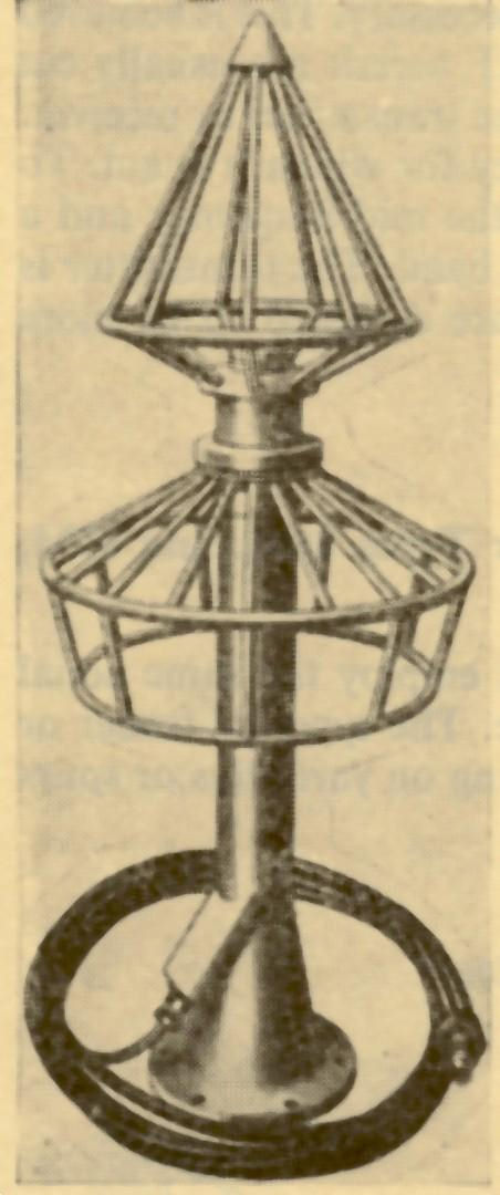
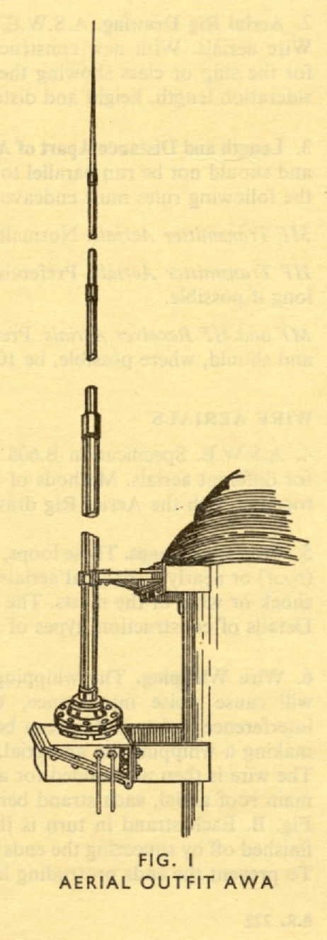
AWA |
Is a permanent receiving aerial fitted in all ships larger than coastal craft. HF/MF with reasonable results down to 100kHz in the LF band.30 foot long. Mounted on a Group 'OA' deck insulator. Becomes an AWA(M) when fitted with light rods (5 in number).
 |
|||
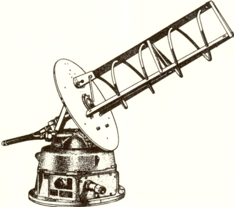
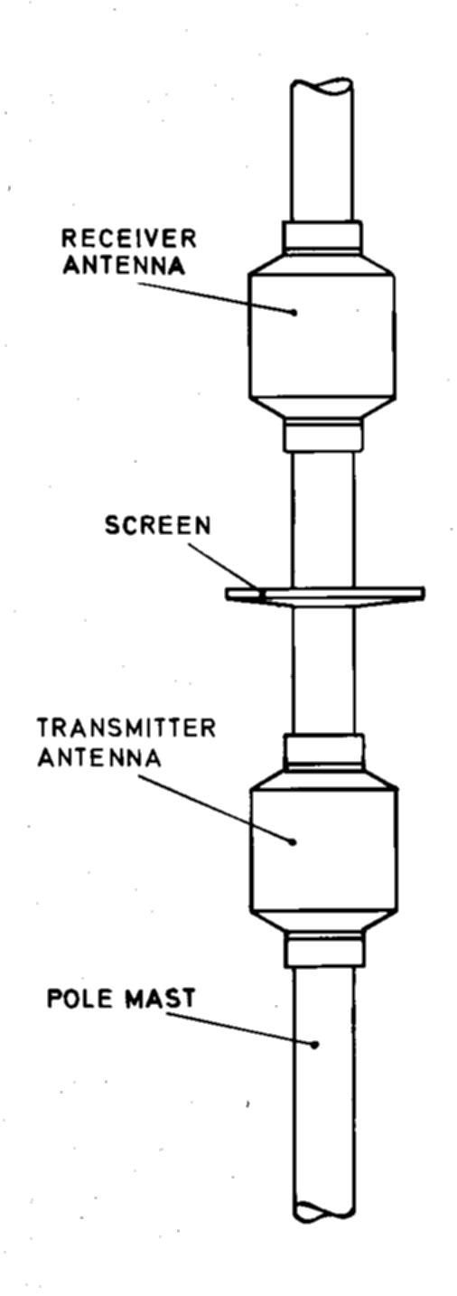
Bellini-Tosi Principle - Loop aerial (System named after two Italian Navl Lieutenants, Bellini and Tosi |
(FMB/FM12) FRAME COIL S19 or S22. S19 fitted CC's and above. Mounted forward in the ship usually in the vicinity of the bridge. Sense aerial built into Loops (F/A & P/S).
 |
|||
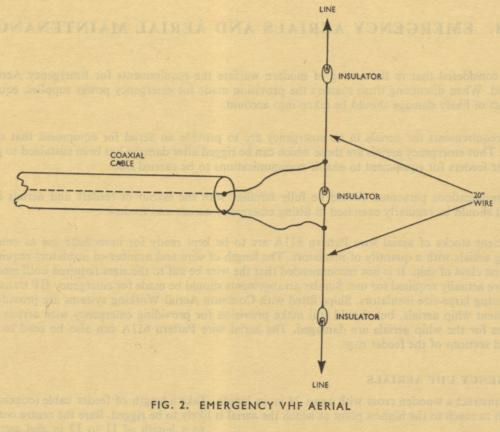
Emergency VHF Aerial |
Jury rig made by the ship's radio operators.
 |
|||
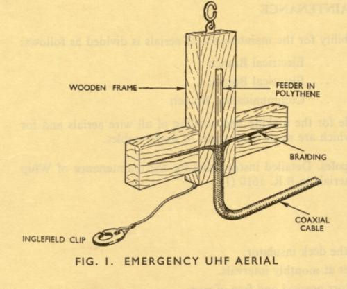
Emergency UHF Aerial |
Jury rig made by the ship's radio operators.
 |
|||
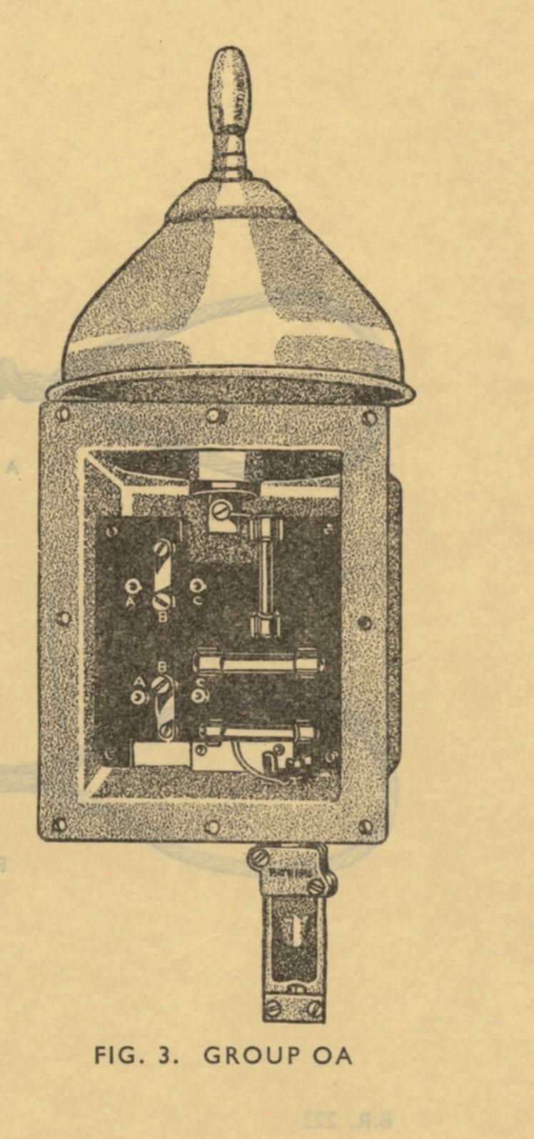
Aerial Feeders and Matching (Receivers) Groups OA, OB and OC |
The correct matching of a receiver to a feeder line and aerial need not be so accurate as with a transmitter. Coaxial cable is therefore used as the feeder line instead of a trunk outfit. The aerial is secured to a deck insulator (DI), the coaxial cable being led from the insulator to the receiver either direct of via a aerial exchange outfit. When the coaxial cable is very long a DI containing a matching transformer (Group OA) is fitted to avoid unacceptable mismatch. Similarly some aerial exchange boards are fitted with matching transformers to allow for aerials normally fitted for Bridge Wireless Office (BWO) reception (ie., for short feed lines) to be used, via the aerial exchange, for a receiver in the Lower Receiving Room (LRR). For receivers in the LRR a Group OA DI is fitted. Two transformers A and B are fitted inside the cover plate and connected to the aerial by means of two 3-position links. Position A = 15 to 1500 kHz = transformer A; Position B = 100 to 10,000 kHz = transformer B; Position C = for above 10,000 kHz = no transformer. The DI's are filled with grease and fitted with a grease nipple. Group OB DI's allow for straight through connections and have no transformers. Normally fitted in large ships for BWO receivers. Group OC DI's is a smaller version of Group OB and fitted in FF's and below. When a matching transformer is used connection is made using low impedance and when not used, connection is by high impedance to the receivers.
 |
|||
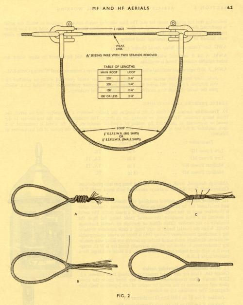
Wire Aerials |
Wire aerials for each ship class were made and repaired as per Admiralty Surface Weapons Establishment (ASWE) Specification B.608. Original fits were supplied by Builders and Dockyards, but thereafter, wire aerials were maintained by ships staff. Because of the exhaust fumes, gases, smoke etc from the ships funnel's and the effects of sea spray, wires aerials had a finite life. Main roofs were changed in their entirety at least once in an eighteen month commission, and main roofs were regularly lowered to deck level piece meal in order that the glass insulators could be washed and returned aloft in good order. Vertical single wire receiving aerials, always sited forward in the ship suffered less from corrosion than did horizontal transmit wires and their associated vertical elements of ships superstructure broadband wires.
 |
|||
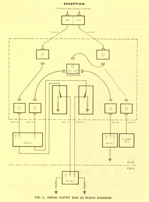
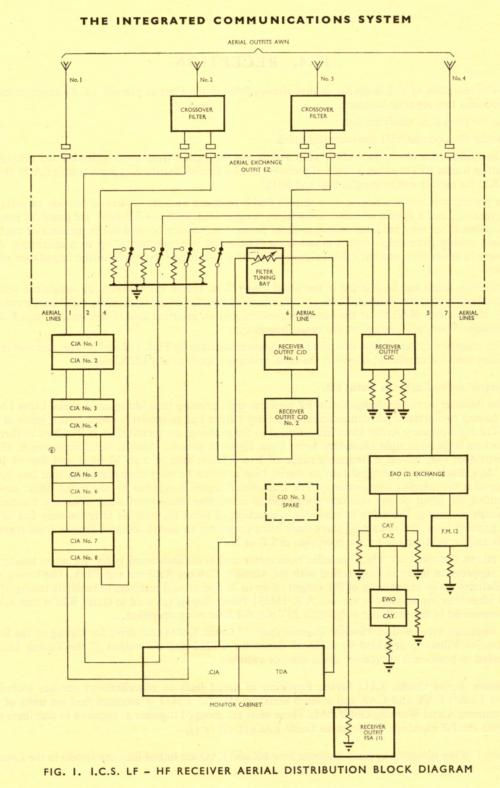
LF/HF Receiver aerial distribution |
ICS1 and 640 transmission with full ICS reception ships. The diagram shows the EZ CAW with an EAO CAW for the older receivers B40 and B41 plus reception for the FM12 MF D/F receiver.
 |
|||
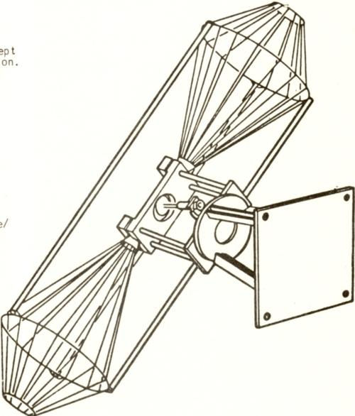
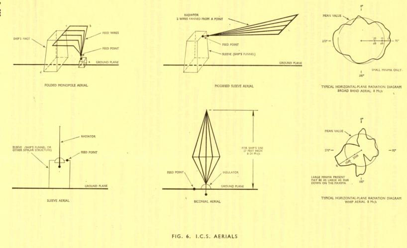
ICS Aerials |
Diagram of early ICS Broadband aerials fitted from the earlier 1960's onwards.
 |
|||
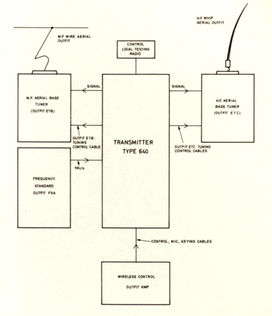
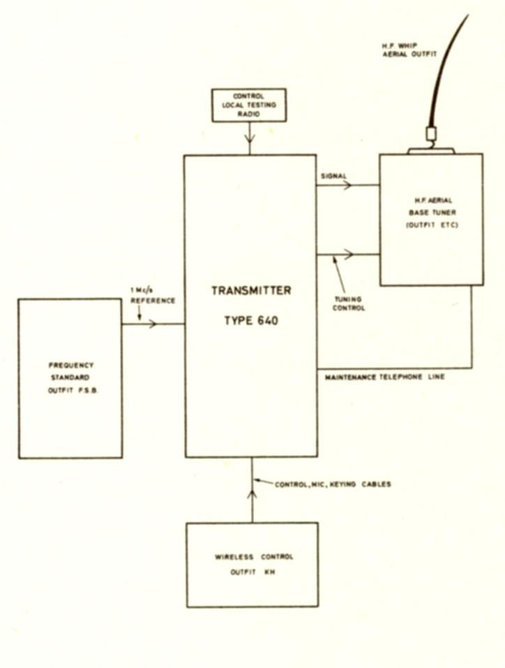
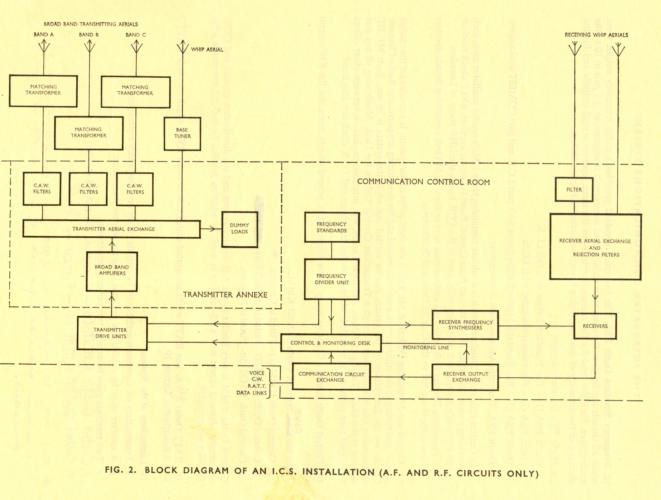
ICS Installation RF and AF paths |
The navigation for radio frequency and audio frequency, transmit and receive in a typical ICS frigate.
 |
|||
AFY |
Shore Station aerial using loop aerials for the directional reception of ship shore which requires less space than the traditional rhombic directional aerial.
|
|||
AJK |
A pole mast mounted wrap-round broadband aerial for transmission and reception of UHF - 225 to 400 MHz.
 |
|||
AWW |
Whip aerial for both transmission and reception. It replaces both the AWF (transmission) and the AWN (reception). HF 1kW 30 foot transmit and receive aerial which, in association with a Group 'OA' deck insulator can be used for V/LF/MF reception. The aerial can be mounted in a fixed position on the superstructure or framework, on a suitable support, or, as a receiving aerial only, on the roof of a 4.5 inch gun mounting.
|
|||
AWY (1) |
This whip aerial replaces the type AWQ. It is an HF 100 watt 24 foot transmit and receive aerial. Although the aerial is normally fixed, it can be hinged
|
|||
AWY (2) |
An HF 16 foot receive only aerial which replaces the shorter rod version of the AWQ as used in CVA and LPH classes of ships and for siting in confined locations where whip aerial outfit AWY(1) cannot be sited because of height limitations at the receiving aerial site. The unit is a permanent fixed receiving aerial which can be mounted on any angle.
|
|||
AWY (3) |
A whip aerial for HF/MF working. 24 foot tall, permanent and fixed self supporting transmit and receive aerial. Completely non-ferromagnetic for use in MCMV vessels.
|
|||
AWH |
Is a 24 foot long version of the AWG (it doesn't use the top three sections). It is used either (a) as the permanent low power transmitter and receiver whip aerial in a small craft and ships; (b) as an emergency transmit whip in large ships when it fits directly on to a 4 inch trunk outfit 'TK' in place of a normal (larger) whip aerial, or (c) with a modified base as the emergency receiving aerial for use with EAL. Light weight rods make it a AWH(M).
|
|||
AJL (1) |
VHF aerial yardarm or spur fitted. A broadband aerial used for transmission and reception 100 to 156 MHz. This aerial differs from the normal cylindrical dipole as the elements consist of flat plates and are manufactured using printed circuit techniques. To protect the elements and to make the assembly of the printed circuit panel sufficiently rigid, the entire assembly is enclosed in a GRP radome. Outfit AJL(2) is non-ferromagnetic and is fitted in MCMV vessels.
 |
|||
UK/SRA-102 |
A UHF (225 to 400 MHz) broadband aerial, transmit or receiver, which replaced the AJE(5). A bi-conical dipole with a counter-poise skirt. Fitted widely in surface ships except MCMV vessels on yardarms and spurs.
 |
|||
AJS |
A UHF (225 to 400 MHz) broadband aerial, transmit or receiver, which replaced the AJE(5). A bi-conical dipole with a counter-poise skirt. Exactly the same as the type UK/SRA 102, but completely non- ferromagnetic and fitted in MCMV vessels on yardarms and spurs.
 |
|||
EBA |
Common aerial working (CAW). Used with type 1203 UHF equipments - 225 to 400 MHz - Provides manual and/or automatic tuned multi-coupler equipment which enable up to twelve transceivers to operate simultaneously from a common receive or transmit aerial in the UHF band. The outfit consists of multi-couplers connected to a single broadband aerial. A receive or transmit multi-coupler may consist of one or two equipment cabinets 6-way and/or 3-way. Each cabinet contains a transmission through feeder, a tuning panel, a power supply and up to six individual multi-coupler units. Manually tuned or automatically tuned units are interchangeable. Each cabinet is dedicated to either transmit or to receive. Associated aerial are AJK or UK/SRA 102.
|
|||
AWT |
The AWT, a 24 foot whip aerial can be assigned as the sense aerial for MF D/F equipment FM16 if a suitable AWN (via EAO) is not available.
|
|||
AXO |
SHF 7 to 11.5 GHz D/F aerial associated with UA3 in surface vessels
 |
|||
AYK |
SHF 11.5 to 18 GHz D/F aerial associated with UA3 in surface vessels.
|
|||
AVK |
This is an Active Receiving Aerial for the frequency range of 10kHz to 30MHz.
|
|||
ETG |
Base Tuner. Automatic aerial tuning unit. Used in conjunction with the aerial AWW. 1.5 to 28 MHz 1 kW PEP.
 |
|||
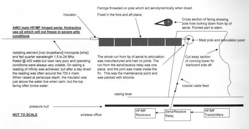
AWO |
A submarine HF transmit and receive aerial working on a send/receive relay. 1.5 to 24MHz - up to 400 watts CW (A1 -Morse Code) only. Associated transmitter 623. Hydraulically raised and lowered to the upright vertical position or 90 degrees clockwise to the horizontal rest position.
 |
|||
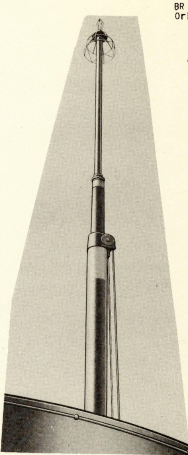
ALE |
Submarine telescopic aerial mast raised and lowered hydraulically in the exactly the same way as for a submarine periscope. Emissions obviously depend upon the submarine transmitter fitted but capable of 500 watts. Has a VHF aerial on the top which is a conical monopole with skirt shaped counter-poise - it has no outfit letters as is known only as Aerial A.P. 67004. Mast originally fitted in the 1950's into 'T' Conversions, and then subsequently, into 'Porpoise' class boats. Normal communications fit is 623 and 86M.
 |
|||
ALG |
Virtually the same as for the ALE, but UHF instead of VHF. Normal communications fit is 623 and 696.
|
|||
EUA (various options) |
Aerial exchange outfits for use in submarines. EUA1 (0 to 50 feet) uses type ALM(1) aerial: EUA2 (0 to 800 feet) uses type ALM(2) and ALY. EUA3 , in addition to aerial exchange, also has signal processing and compensating facilities.
 |
|||
AJP |
A submarine aerial for combined HF and UHF working and for NAVAID reception.
 |
|||
ALF |
Aerial outfit ALF is a loop aerial system for the frequency range of 15 to 550 kHz designed for use in certain submarines in conjunction with the receiver Type B41. Submarine Aerials of Old - Before, during and after WW2, submarines had 'jumping wires' which were rigged from forward to aft external of the boat, over the top of the casing and the conning tower. The conning tower was fitted with stanchions which supported the wire, set in such a way that personne and equipment (periscopes etc) were not affected by the presence of the hefty wire.
The function of the wire was to support a loop aerial in the forward section (i.e. bow to bridge (conning tower) which would act as the receiving aerial when dived. In earlier fits, the Captain had to point the boat towards the direction of the transmitting source to maximise the strength of the received signal. The file Submarine Aerials shows two fits showing the jumping wire. The first picture comes from a book called the "U-Boat Commander's Handbook' and shows a U=Boat drawing, dating from 1943. The wire can clearly be seen in the top picture. The second picture is of a British 'A' Boat not yet modified to have a sail-fin. It is of HM Submarine Alaric in Malta. The stanchions and the wire are very clear. The third picture is one of Alaric's sister boat the Alderney. She has a sail-fin and no jumping wire. Her loop aerials Forward-Aft and Port=Starboard are sited in the top of the fin, F-A forward and P=S aft. They fed the outfit Type ALE. The fourth picture shows the actual loop aerial, was a continuous cable, part secured to the bow-to-stern support wire, part on or under the free flood casing/conning tower area and in a very simple drawing, looked like this.
|
|||
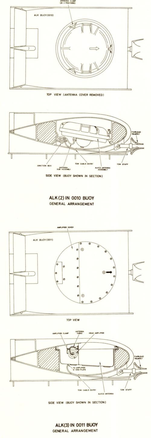
ALK 2 and 3/ type ALL |
A buoy aerial system fitted in submarines. Used by receiver CFA. VLF reception on 15 to 25 kHz.
 |
|||
ALM 1 and 2 |
Submarine receiving aerial, fin mounted, VLF/LF 10 to 200 kHz - used with CJD receiver.
 |
|||
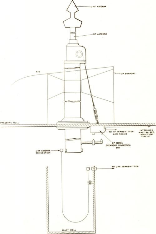
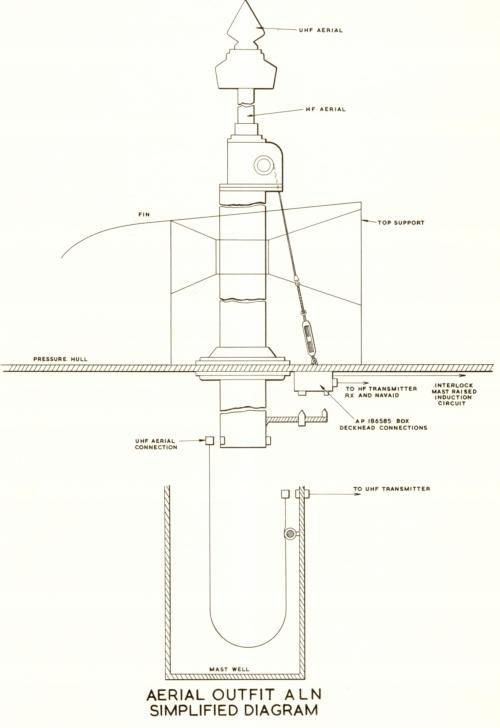
ALN |
Submarine telescopic aerial for HF 1.5 to 24 MHz, UHF 225 to 400 MHz. Associated equipments 623 and 696. Mast replaces the ALG
 |
|||
ALY |
Submarine fin mounted reception outfit for VLF/LF - 10 to 200 kHz
 |
|||
ALZ |
Submarine fin mounted reception outfit for VLF/LF - 10 to 200 kHz
 |
|||
AYF - Used for UA also |
A fixed SHF D/F aerial fitted in submarines for use with UA2
 |
|||
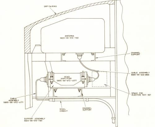
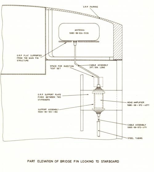
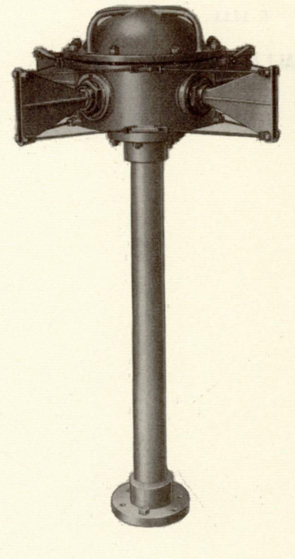
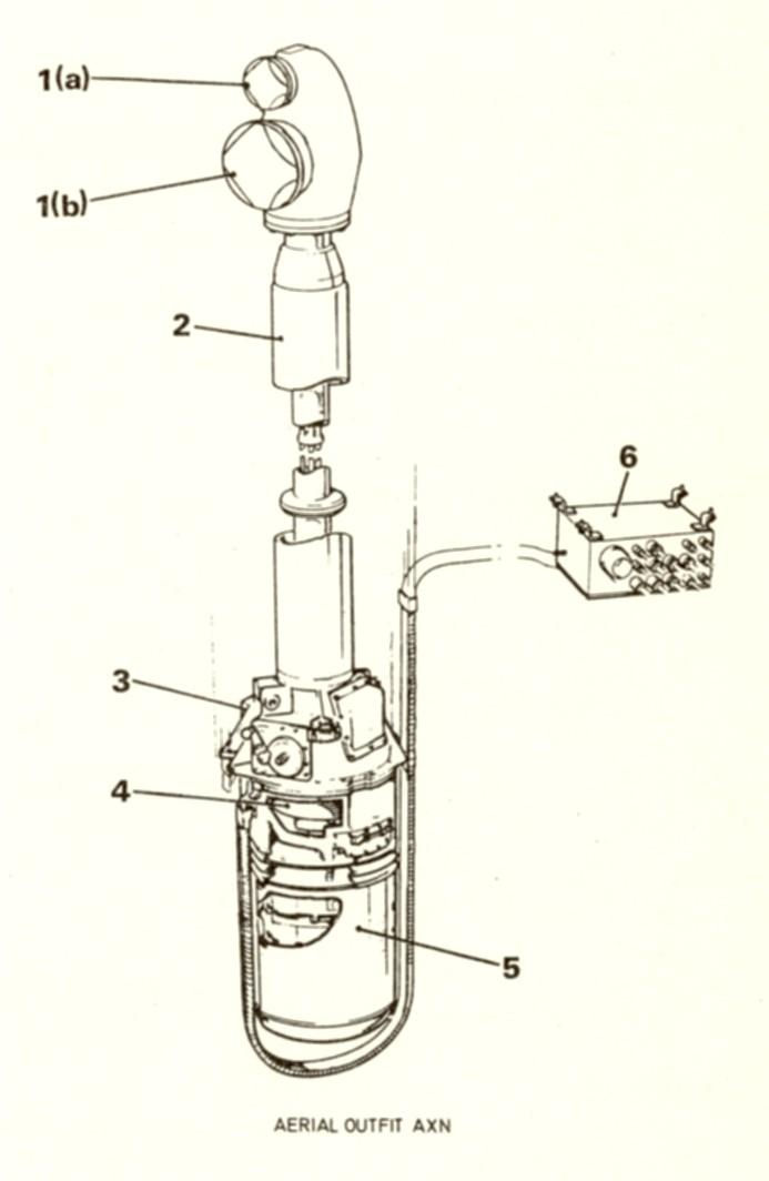
AXN |
A D/F aerial used in submarines for UA12
 |
|||
Frame Coil (Bellini-Tosi Princple) |
Submarine fitted M/F D/F set (FMA/FM11) loop aerial type S21. Submarines fixed aerial (jumping wire) was used as the sensing aerial.
|
|||
AYG and AYH |
AYG and AYH used for D/F equipment UA4 in submarines. Mounted on top of a telescopic mast hydraulically raised and lowered known as the Shuff-duff (SHF) mast, the forward mast.
|
|||
EAG/W/J |
ype 692 and 693 common aerial working (CAW). Up to six transmitters (692/3) or receivers (CUJ can use one aerial outfit AJE. These are automatically tuned outfits, the EAG = 2 TX/RX; EAW = 4 TX/RX and EAJ = 6 TX/RX
|
|||
EAN/P/Q |
Type 692 and 693 common aerial working (CAW). Up to six transmitters (692/3) or receivers (CUJ can use one aerial outfit AJE. These are hand tuned outfits, the EAN = 2 TX/RX; EAP = 4 TX/RX and EAQ = 6 TX/RX
|
|||
AWC |
Uses the same aerial as type AWF but designed for fitting in aircraft carriers. The aerial is mounted on a hinged pedestal, which allows it to be lowered to the horizontal when flying ops are in progress. It is hand operated.
|
|||
AWL |
Uses the same aerial as type AWF but designed for fitting in aircraft carriers. The aerial is mounted on a hinged pedestal, which allows it to be lowered to the horizontal when flying ops are in progress. It is hydraulically operated. Can be operated from a remote position e.g., the FLYCO position on the bridge/island and is fitted in preference to the AWC when whip aerials are used as supports for wire aerials.
|
|||
AWG |
Is a 36 foot long aerial in nine 4 foot sections. A lighter steel whip for use with transportable HF transmitters e.g., Type 612ET, with a power output of up to 40 watts. Also used as an all-wave receiving aerial.
|
|||
AWJ |
This is an emergency HF aerial for transmission and reception for use in submarines when surfaced only. It is a hand erected, telescopic whip aerial consisting of five sections. When collapsed, the first four sections (top down) fit inside the bottom section. It is sited on top of the fin. When extended it is 25 foot 6 inches tall and when retracted 6 foot 8 inches tall. Rarely used, except for evolutions, it was nonetheless always raised on "shut off from diving" being ordered en-route back to harbour, and used as a vantage position from which to fly the boats commissioning pendant.
|
|||
AWM |
A 24 foot whip aerial used with NAVAID equipments when no other suitable receiving aerial is available.
|
|||
Aerial Feeders and Matching (Transmitters) TK, TA, TL, TC |
A trunk outfit is used as the feeder between a transmitter and its aerial, the trunk being either circular, 'D' shaped or rectangular in shape. The conductor from the transmitter to the aerial is supported in the trunk by means of stand-off insulators and the aerial is connected to a deck insulator (DI) at the top of the trunk. The size of the trunk depends on the power of the transmitter as follows:- low power HF = 4 inches = TK; low power MF and medium power HF = 8 inches = TA and TL; medium power MF = 18 inches = TC
|
|||
EE, EF, EJ and EL |
Manual Receiver Aerial Exchange Outfits. These outfits, allowed any aerial in the surface ship to be plugged (plug and jack connection) to any receiver. 'EE' for small ships; 'EF' for DD's and FF's; 'EJ' for CC's and RR's and 'EL' for Leaders. All these pre-date ICS equipments from the early 1960's onwards.
|
|||
ALJ |
Submarine stub aerial for UHF working with 696. 225 to 400 MHz. Only three units were manufactured.
|
|||
ALO |
Submarine fin mounted receiving aerial for VLF/LF 10 to 200 kHz - used with outfit CJD.
|
|||
AWQ |
The main transmit and receiver HF/MF aerial in a small craft where the distance to the transmitter is less than 20 feet. It replaces the AWH which was a trunk system, the AWQ having a coaxial cable in lieu.
|
|||
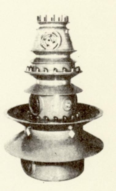
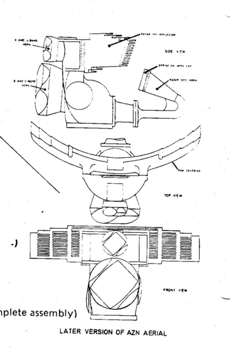
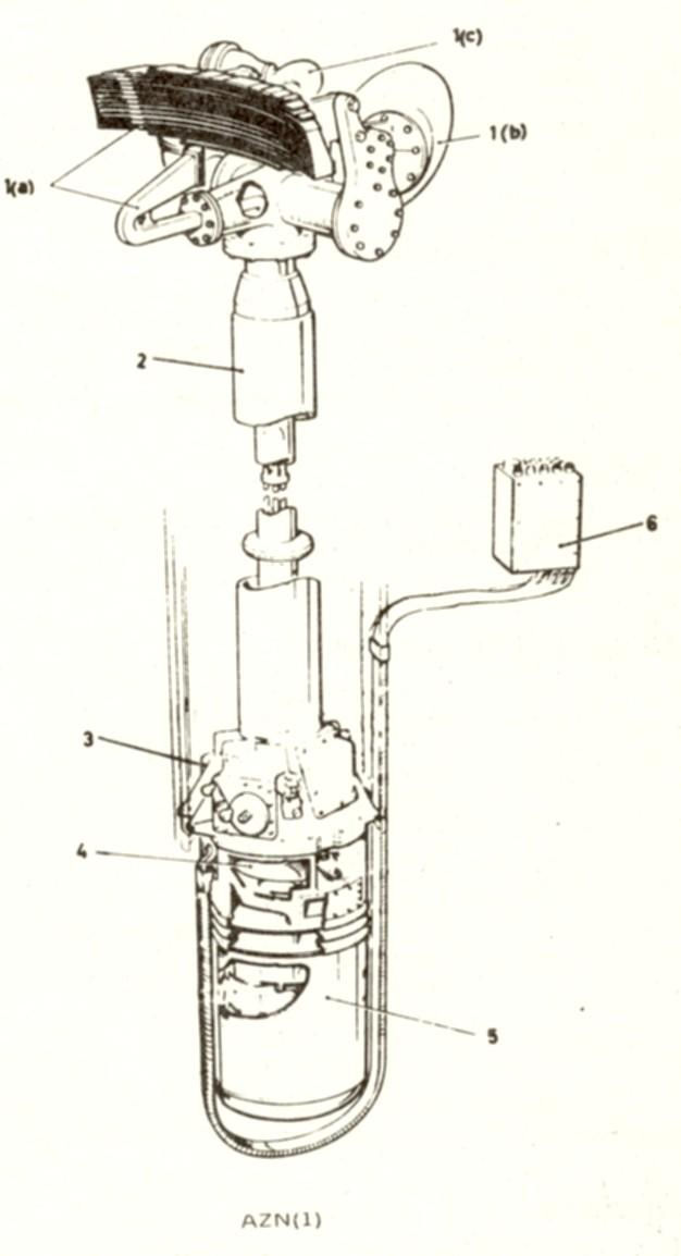
AZN |
Submarine fitted. A joint D/F and Radar aerial.
  |
|||
ETF |
Base Tuner. 1.5 to 24 MHz up to 1 kW PEP. Associated with several transmitters.
 |
|||
ALP |
Submarine buoy aerial for VLF/LF/MF reception with receiver CJD
|
|||
ALQ |
Submarine buoy aerial HF transmission 2 to 30 MHz to 1kW PEP (SSA) and for VLF/LF reception using CJD
|
|||
AWU |
Submarine special purpose whip aerial for NAVAIDS - mounted on telescopic mast.
|
|||
ALT |
Submarine fitted - floating wire for VLF reception
|
|||
ALU |
Submarine fitted - floating wire for HF/MF reception
|
|||
AN/BRA |
Telescopic radio mast hydraulically raised and lowered on a submarine. HF transmission and reception 2 to 30 MHz up to 1kW PEP.
|
|||
AFA |
Shore Station Fit. Omni-directional HF receiving aerial. It consists of a horizontal, full wave cage dipole with two arms arranged at right angles. The aerial is directly connected via a matching unit to a coaxial cable. Supplied with four assemblies W = 1.5 to 3 MHz; X = 3 to 6 MHz; WX Construction 3 x 110 feet and 1 x 70 foot timber lattice towers. Y = 6 to 12 MHz; Z = 12 to 24 MHz; YZ Construction 3 x 41 feet and 1 x 23 feet masts.
|
|||
AFB |
Shore Station Fit. A horizontal dipole with reflector used for long distance directional reception. The aerial is used in conjunction with aerial outfit AFC with which it is similar in layout and dimensions. The receiver is coaxially fed, necessitating the use of a coupling match unit. Spot frequencies between 5 and 20 MHz. 80 to 180 foot masts depending upon frequency.
|
|||
AFC |
Shore Station Fit. Horizontal dipole with reflector used for long distance directional transmission. Use in conjunction with aerial outfit AFB. Spot frequencies between 5 and 20 MHz. 600 ohm transmission line. Mast height 80 to 180 depending upon frequency used. Rated @ 10kW
|
|||
AFD |
Shore Station Fit. Vertical half wave transmitting dipole 'Y' matched to 600 ohms transmission line used for broadcast. Rated @ 10kW. Spot frequencies between 5 and 20 MHz. Mast 80 to 180 depending upon frequency used.
|
|||
AFE |
Shore Station Fit. A vertical quarter wave transmitting aerial used for broadcasts. Spot frequencies between 2.3 and 4 MHz. Rated @ 7kW. Mast 80 to 110 foot according to frequency used.
|
|||
AFF |
Shore Station Fit. Quarter wave transmitting and receiving vertical aerial used for broadcast. Spot frequencies between 1.5 and 20 MHz. Rated @ 500 watts. 80 to 180 foot mast according to frequency.
|
|||
AFG |
Shore Station Fit. Quarter wave transmitting and receiving aerial for ground to air communications or broadcasts. Spot frequencies between 3 and 20 MHz and rated @ 500 watts. Mast height 55 feet.
|
|||
AFH |
Shore Station Fit. End fed half wave vertical transmission aerial for local ship shore communications. Spot frequencies 1.5 to 4 MHz and rated @ 350 watts. Mast height 180 to 350 feet according to frequency.
|
|||
AFJ |
Shore Station Fit. Two wire transmitting rhombic aerial used for long distance directional communications. 6.6 to 20 MHz and 10kW. Mast height 110 feet.
|
|||
AFK |
Shore Station Fit. A vertical folded terminated transmitting dipole used for broadcast transmission. 3:1 frequency ratio in HF band. 10 kW. Mast height 80 - 180 feet according to frequency.
|
|||
AFL |
Shore Station Fit. Horizontal receiving dipole used for point to point circuits. Spot frequencies between 5 and 20 MHz. 80 to 180 mast depending upon frequency.
|
|||
AFM |
Shore Station Fit. Horizontal transmitting dipole used for point to point circuits. Spot frequencies between 5 and 20 MHz. 10 kW. Mast height 80 to 180 feet according to frequency.
|
|||
AFN |
Shore Station Fit. Single wire receiving rhombic for long distance directional communications. 6.6 to 20 MHz. 80 foot mast.
|
|||
AFO |
Shore Station Fit. Horizontal folded terminated receiving dipole used for reception over a wide frequency band. 3:1 frequency ratio in the HF Band. Mast height 80 to 180 feet according to frequency.
|
|||
AFP |
Shore Station Fit. Four wire transmitting rhombic used for long distance directional communications. 6.6 to 20 MHz rated at 10kW. Mast 110 feet.
|
|||
AFQ |
Shore Station Fit. Single wire receiving rhombic for long distance directional communications. 6.6 to 20 MHz. Mast 78 feet. Adastra.
|
|||
AFR |
Shore Station Fit. Three wire transmitting rhombic for long distance directional communications. Frequency depending upon construction of aerial. 40 kW. Mast 110 feet high.
|
|||
AWK |
12 foot long stainless steel whip aerial for use in Mobile Radio Van 45.
|
|||
EAA |
Common aerial working (CAW) for VHF transmitters 8C for Type 87M between a minimum of two and a maximum of eight, can work into a single aerial. Similarly, between two and eight receivers P104 for receiver outfits CDU may be fed from a single aerial. EAA = 2 x transmitters 8C into a single aerial. Associated aerial are APH ARU ANC and ANZ.
|
|||
EAB |
As above EAB = 3 or 4 transmitters 8C into a single aerial
|
|||
EAC |
As above EAC = 5 to 8 transmitters 8C into a single aerial
|
|||
EAD |
As above EAD = 2 receiver CDU from single aerial
|
|||
EAE |
As above EAE = 3 or 4 receiver outfits CDU from single aerial
|
|||
EAF |
As above EAF = 5 to 8 receiver outfits CDU from single aerial
|
|||
AHR |
The FULL wire main roof of a modern ship including the HF broadband aerial wires, spreader plate and insulators.
|
|||
AHT |
Main roof wire aerial associated with the MF base tuner ETB for 240 kHz to 3 MHz working
|
|||
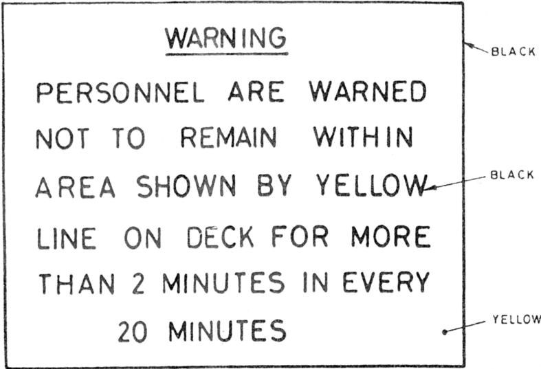
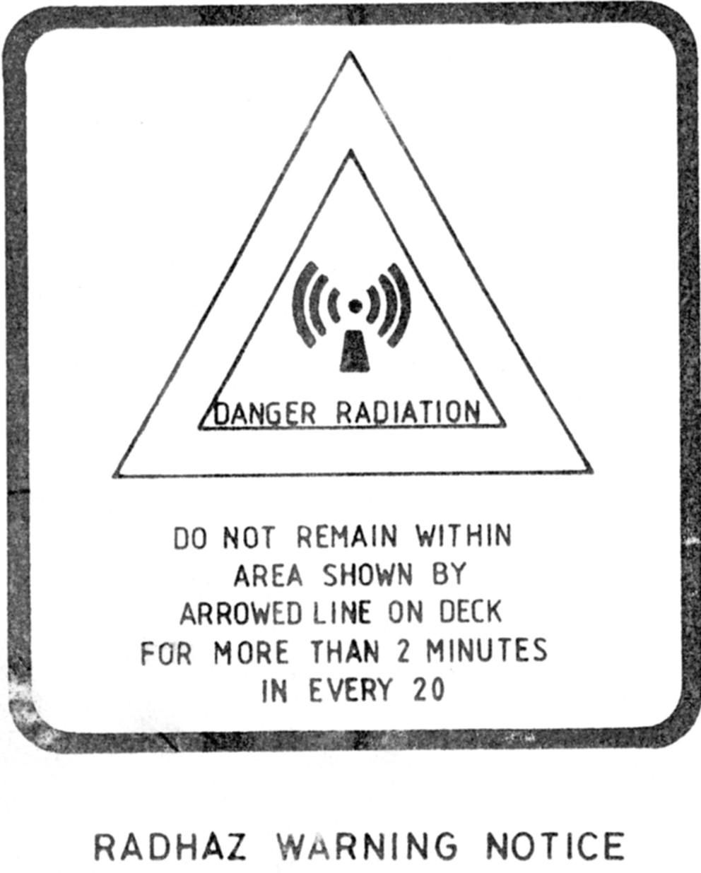
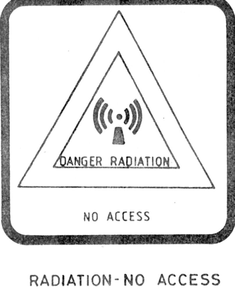
RADHAZ |
Radhaz (Radiation Hazard) is a very important part of the general upper deck management of a warship with its many aerials, some fixed and some rotating. It also concerns itself with underwater transducers transmitting sonic waves - SONAR. The prime purpose of a RADHAZ organisation is to protect personnel from harmful electromagnetic radiations whilst working aloft, as well as protecting munitions from premature ignition when in range of the harmful radiations. Additionally, on decks routinely accessible to personnel which have transmitting aerials, there are fixed and permanent precautions taken to protect personnel from shock and radiation.
This file covers all the main points of that management in a modern heavy destroyer, a DLG, of the 1960's.RADHAZ Pages 5 and 6 of the file should be printed and married together so that Part C (page 6) fits snugly with Part A (page 5).
   |
|||
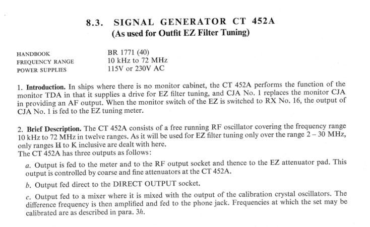
CT452A |
Used for tuning EZ filter in a Standard 3B ship with 640 transmitter and full ICS reception.
 |
|||
AE Base Tuner |
For further details of Aerial Base Tuner
|
|||
AE Tuner Unit SSA |
For further details of Aerial Tuning Unit SSA
|
|||
Multicoupler RX AE |
For further details of MultiCoupler Receive Aerial
|
|||
Aerial Technology of long ago. War years to 1950's |
For further details of Aerial Technology
|
|||
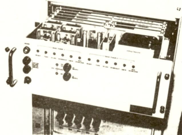
HMS SHEFFIELD Project of the early 1950 |
The original sea trials for HF CAW were conducted in HMS Sheffield in the early years of the 1950's.
|
|||
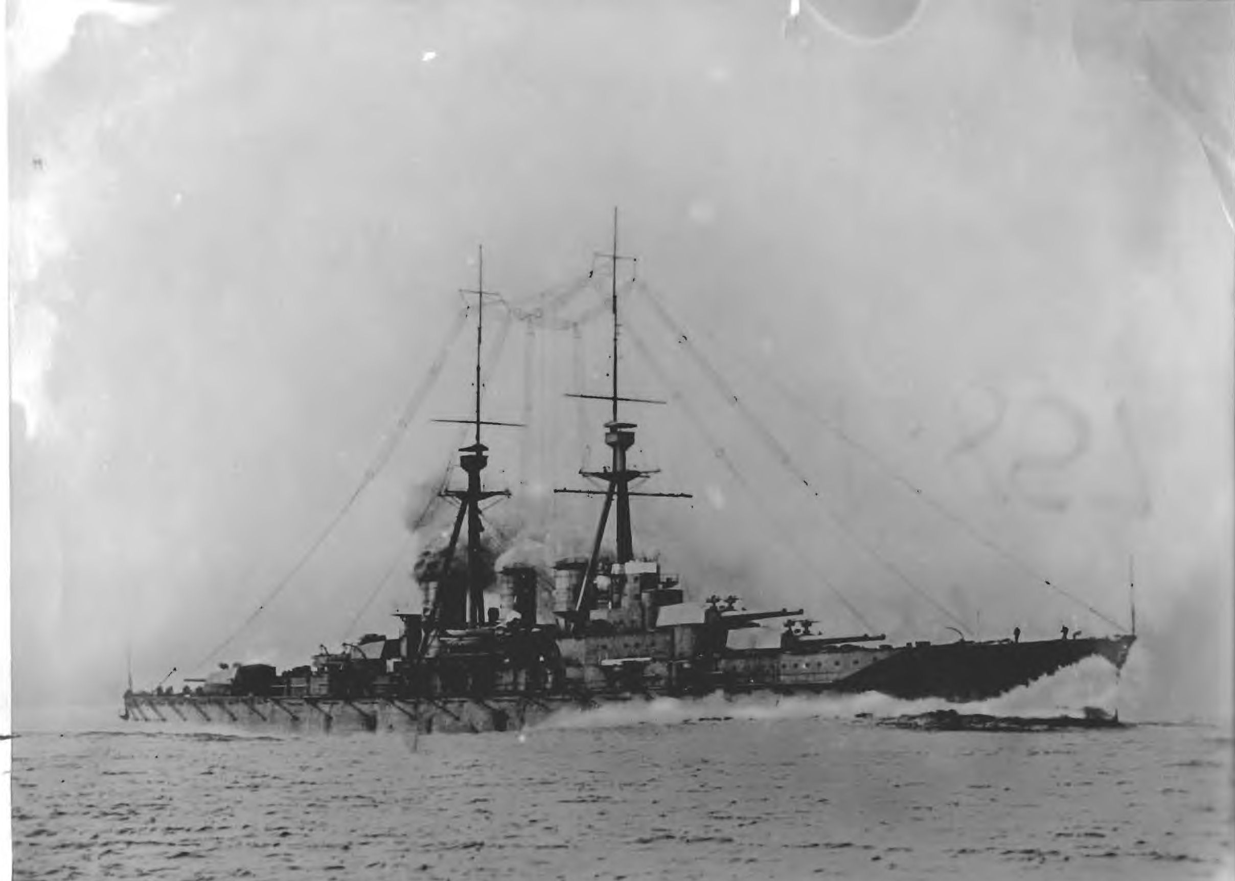
Early Rigs |
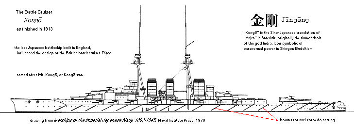
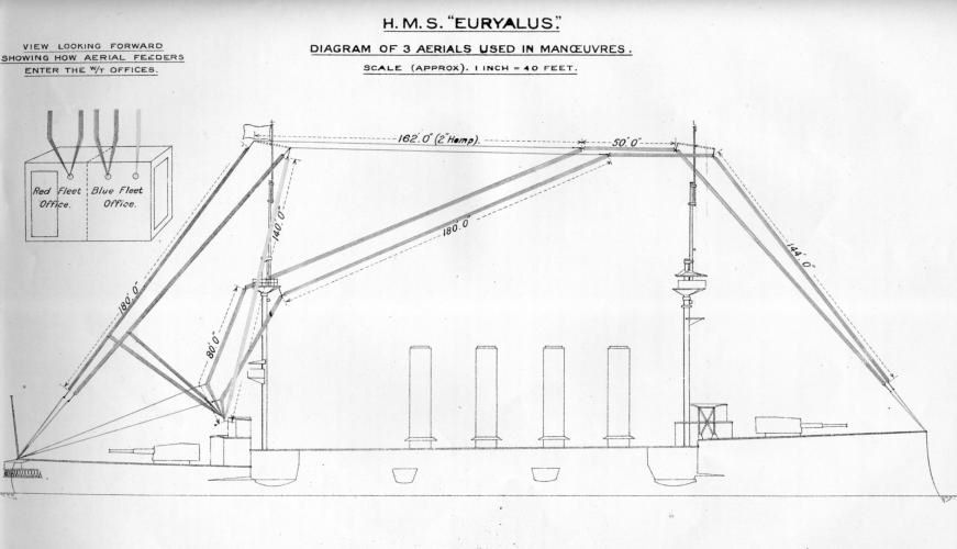
Here are two good examples of early aerial rigs at a time when clearly there was no shortage of wire, and certainly there was an abundance of rigging skills in our dockyards. Both are circa 1913. One is the Euryalus and the other the Kong�. Euryalus is in the form of a jpeg and its story (and this picture) features in the 1913 story of Naval W/T on this site. Kong� is published as a PDF because I want you to zoom in on all that beautiful 'knitting' or aerials aloft. In my time I have taken part in main roof aerial rig changes in big ships like the Depot Ship Tyne and to a lesser degree in a Type 12 frigate (Rothesay) , a cruiser (Tiger) and of course, a submarine jumping wire which runs forward to aft over the top of the periscope stanchion's, but this has no competitors! Kong� carried more wire aloft than any other ship in all history of W/T fits.
The Japanese Battle Cruiser Kongo - was a warship of 20,000 tons, was fitted out by the Marconi Company in 1913 with a main installation of 25kW and a special 1.5kW installation for short range traffic. Double-T aerials seen the photograph below are of the cage type supported by spreaders 25 feet in length at the top of two masts each 180 foot high with extnesions forward and aft. The 25kW transmitter is installed two decks below the upper deck and operated from below in war conditions. A spacious operating cabin is also provided on the upper deck from which the main set is controlled in time of peace, and here also is installed the 1.5kW set, together with an oil engine from which power may be obtained in case of failure of the mains supply. The 25kW set is of the standard Marconi synchronous spark pattern with automatic wave change apparatus and has a range of approximately 1000 miles. Kongo was fitted out in the UK post build before leaving for Japanese waters and trials.
For the record, Nelson's Column is 185 ft high with Nelson himself adding a further 17 foot, an overall height of 202 ft. Can you just imagine that ship ?
   |
|||
HMS Royal Oak |
Our first casualty of WW2, which was sunk at Scapa Flow by a German U-Boat in 1939. She had two TR's, No 1 with a Type 36C TX and No 2 with a Type 49C TX, and these drawings from the Signal School in Portsmouth date from December 1935. In the third picture showing her rigged with experimental wire aerials in 1937 note the two TR's and their respective positions on that same deck with the upper one (No 1 on the port side) and the lower one on the starboard side. Apart from No 1 and No 2 main aerials, note the auxiliary aerial trunk and the enormous size of the Port Trunk at a whopping 18 inches.
|
|||
HMS Iron Duke |
The Iron Duke was the same generation of ships as the Royal Oak above, only two years older having been completed in 1912. This file shows Fig's 1-3 of her experimental wire aerial rig in 1937, drawing produced by the Portsmouth Signal School.
|
|||
EAA, EAB, EAC, EAD, EAE, EAF |
1950 style VHF CAW
|
|||
1901 Aerials |
|
|||
Aerial bits and pieces 1906 |
|
|||
Aerial bits and pieces 1912 |
|
|||
Aerial bits and pieces 1920 |
The 1920 version of the W/T Manual we have has a 'sad' stamp of ownership printed on the inside cover. This is it Click to enlarge
It once belonged to HMS Glorious when, as built, she was still a Cruiser. In the 1920's, completing in 1930, she was converted into a Carrier. Very early in WW2 (1940) she was sunk by the German ships Scharnhorst and Gneisenau in the Norwegian Sea.
|
|||
Aerial bits and pieces 1931 |
|
|||
UHF Aerials |
|
|||
Shore Station Aerials |
|
|||
Wire Aerials in 1945 |
This much used pamphlet has seen better days, and is quite literally dropping to pieces, eventually to turn into dust. It has to be rescued and digitised now before its contents are lost for ever. To those of you who are familiar with wire aerials in warships, you will know that a 'B608' was always the master document of reference, and every type of ship had its own B608 drawing. This document generalises on the subject of wire aerials, pointing out that whip aerials are currently under development and that a separate specification (Specification B493) will be issued for their fitting in due course. This document was written in April 1945 with world war two still being prosecuted. Its preparation therefore is clearly a pukker WW2 document. However, the Addendum's post date that period/crisis, being dated from 1949 to 1952.
Details of Wire Aerial B608 circa 1945 see this file (PART 1) Details of Wire Aerial B608 circa 1945 see this file (PART 2)Arial Nomenclature - specifically that referring to chunks of naval metal which are known to emit or receive radio waves.A device which emits and receives radio waves is an A E R I A L - full stop. If you were a German or a French man you would say Antenne; if a Spaniard ANETNA (one letter N) and if an Italian ANTENNA. Marconi (an Italian) is known as the father of radio communications, but, in the Royal Navy, Admiral of the Fleet H.B. Jackson (then Captain Jackson R.N.) had as much to do with radio communications as did Marconi, at least in the embryonic days of the late 1890s. Unfortunately for use, our American friends copied the Italians, but we Brits say AERIAL. This little opening paragraph is taken from Chapter XVI of the RN W/T Manual dated 1920.Quote from Chapter XVI - "AERIALS AND EARTHS - 484. We will now consider the principles of design and construction of the aerial wire system, usually known as the "aerial" in the Service, and as the "antenna" outside the Service" |