
Wireless Telegraphy 1910
Written by Godfrey Dykes
© RN Communications Branch Museum/Library
The contents of this file 1910/1 are listed below. |
| General Summary. Most of 1910 devoted to standardising the main W/T fits at sea, viz Mk1* and Mk11, and organising a proper stores/spare parts system. No new apparatus.
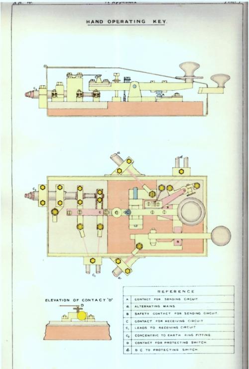
The Mk1* operating switch is superseded by a hand operating key which does the job of sending Morse and the OPERATING SWITCH - Further details. (A résumé. In the beginning, operators used a mechanical device (hand lever and foot pressure switch) to change the aerial from transmit to receive and back again - Further details.
Then in 1909 the mechanical was change to electrical and a new C.O.S. was commissioned). Now the HAND OPERATING KEY part of which (it has two Morse keys) will do the Morse sending the other part (key) with operate the aerial between transmit and receive.
New revolving spark gap.
Improved aerial feeder to cut down on losses.
Problems for operators - ventilation in Silent Cabinets and W/T offices (same area) very poor. Major rethink to solve the problem.
Crystalite Detectors at sea in Type 'B' receivers highly successful. All ships to be issued with a new receiver, Type 'C' which has the Crystalite Detector incorporated. However, a new Detector called a 'Zincite-Tellurium' looks set to replace the Crystalite Detector in the new Type 'C' receiver.
61 destroyers now fitted with W/T, plus 2 Australian Destroyers HMAS Paramatta and HMAS Yarra which have been fitted by the Marconi Company.
9 Portable and Harbour Defence kits now in the Fleet, but problems with manufacturing suitable power supplies. 9 Short Distance sets are installed and on trial at sea. (You will remember that they are using the 1.75MHz frequency ground wave). Ready to fit all big ships with Short Distance sets but that will require many extra operators and they have not been earmarked or approved - major set back!
Naval airships to get a W/T installation using a quenched spark set (no, nothing to do with buckets of water!). An airship is being built at Barrow-in-Furness where trials have been conducted. Of the quenched spark, they say that much experimentations is to follow but that there is little doubt it will be smaller, lighter and far more efficient than current spark W/T.
Three new low power shore stations due on stream next year.
Malta high power station experiencing problems with power supplies and severe atmospherics - delayed working until end of next year.
Experiments into spark photography at Cleethorpes.
Service wavelengths and long distance signal codes to be altered.
The fist five warrant officer telegraphists (one failed his course) have qualified and have been appointed. Telegraphists Branch showing increasing numbers but still short of man power. Training results and telegraphists at sea very satisfactory.
Officers to be given courses in W/T to qualifying for Lieutenant (S) - for Signals - and the first class has started training (1910) in HMS Vernon (note that their course is listed below).
Instructional Report on officers/ratings training in the W/T section of HMS Vernon. Note 30 PO Tel's (NS) - New Style. Old Style (OS) were volunteer PO's from other Service Branches in the changing-over period system - Further details. Instructional Report from HMS Defiance.
Telegraphists Branch. PO Tel's still out number Ldg. Tel's.
HMS Vernon under pressure on the training front. Devonport ratings qualifying or re-qualifying (mandatory within four years of first qualifying and subsequently thereafter) under the new system (NS) and all Coastguards will now train at Devonport onboard HMS Defiance. Portsmouth and Chatham ratings will continue to train in HMS Vernon.
HMS Impregnable's Report of Boy Tel's training. 249 boys trained to date. Now 17 boys per course. 50 discharged from their studies, 1 of them DD. DD = Discharged Dead, has been used in the navy for many a long year and can best be seen in the record of HMS Victory immediately after the Battle of Trafalgar. In those days the 'D' for dead was dreadfully apparent, and the 'D' for discharge meant being thrown overboard without ceremony, Christian or otherwise. Boys taught coding and decoding.
Report on W/T Conference held at Torbay - a regularly used place for Fleet Reviews in the Victorian-George V period. Good results achieved in the Fleets due in equal part to the equipment provided and the expertise and diligence of the men operating it. However their numbers are short and their efforts could not be maintained for a lengthy period of time.
Short Distance Wireless - a high agenda subject of discussion. Stumbling-block to fitting the whole Fleets was the lack of telegraphists to operate them. Supply the telegraphists first and then the equipment was the unanimous opinion.
Signal Book and wavelengths debated. Admiralty messages to the Fleets and the receipts back, to be modified. More transmissions from Cleethorpes and more frequent reception periods for ships. Cleethorpes hasn't got enough power to increase transmitter time on air - it is supplied by the Grimsby Public Utilities - and anyway, it is also busy with Gibraltar as well as with ships.
High Power stations to send out traffic lists to (a) the Fleets and (b) to detached ships/squadrons at different listening periods - to Fleets, every half hour and to others, every two hours counting from noon GMT. Traffic Lists (so common to merchant navy operators) have a parallel in that Submarine Broadcast Procedures used them during the period 1950-1970) avoided ships listening just in case there was a message for it.
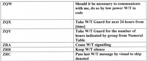
The use of 'Z' and other 'Z Groups'. The letter 'Z' transmitted singularly (at least by Morse) meant only one thing to most of us and that was a FLASH signal, the highest of all priorities/precedences when the world 'stopped' to allow pre-eminence to the signal passing from originator to action addressee often over several routes/circuits. In 1910, it meant something very different - more in a minute. The group ZUZA meant "am about to send", to transmit, and a new group ZUYU was to mean "am not going to send till the next half hour". At the end of every half hour, Cleethorpes would transmitter the letter 'Z' denoting "nothing more coming" - QRU in today's terminology: Further details for use of the group ZUZU.
When a Fleet was within range of a Medium Power shore station, the ship detailed to receive messages from Cleethorpes (the 'X' Tune (98kHz) Guardship - think of it as the Fleet Broadcast), upon hearing the letter 'Z' (QRU) would revert to 'W' Tune (151kHz - think of it as a ship-shore) manned by the Medium Power station and transmit the letter 'D' followed by the time of the origin of the message it was acknowledging as having received. This had to be done before the next half hourly schedule on 'X' Tune to which the Guardship returned as soon as it had sent its 'D' signal. At 6am daily, Cleethorpes is to send a series of V's for five minutes before making either the ZUZA or the ZUYU signal. The V's were used by the operators to correctly tune in their receivers.
But, what if the Fleet is dispersed outside V/S range where a single 'X' Tune Guardship couldn't pass traffic received to other ships?
Answer! If spread to 5 miles between ships, received signals to be sent on the Short Distance set/Tune. That means the expediting of this equipments fit poste haste. If the spread was outside 5 miles, the C-in-C could approve the use of other (not normally used) wavelengths like 'R' and 'T' (378kHz & 234kHz) in addition to normal Service wavelengths and thereafter, to employ the "GROUP SYSTEM". Let us go back to that colour coded diagram which heads-up this page. This is one of their Group Systems. It is meant to represent the axiom 'a picture saves a thousand words' which for the most part, it does. All the ships in Group A communicate together and any messages for Group B or the C-in-C are collected by the Senior Officer and sent to the Flagship on 'S' Tune. This is the same for the ships/messages in Group B. Incoming messages from shore which concern ships in either group are passed by the Flagship on 'S' Tune. The important point is that the C-in-C, whilst out of sight of his ships, has a window to keep in touch with shore (the Admiralty); a window for 'spuds-and-bread' traffic from half his ships at a given time and a window for the other half but at a different time, and a window, shut for a few minutes every half hour, to receive signals from his two groups of a more URGENT TACTICAL nature.
ROUTINE messages are Position Course and Speed (PCS), consumption of coal or oil, merchant vessels observed and weather reports. IMMEDIATE message were for reporting a sighting of the enemy.
Shore Station NOT to use the Silence Sign. The Silence Sign, then as in later times was HM run together and repeated until all stations stopped sending. Silence could only be lifted by sending the 'reverse' signal for which there was no recognised written down signal i.e., as HM was 4 dot's and 2 dashes repeated, the reverse was 2 dot's and 4 dashes repeated. In the ASM (Allied Signal Manual) of WW1, the Morse sign of 4 dashes sent by V/S = MM =Code Flag and if sent by W/T as an International Signal it meant CH, so we could say that 'IMM' or 'ICH' was the reverse of HM. However, listen to these two sound files, the first Imposing Silence and the second Lifting Silence. Later, the navy chose HM run together followed by a space repeated twice more (three times in all) and if that was not adhered to, three more HM's were transmitted etc. To lift silence, the navy used the opsig ZUG (meaning NO, NEGATIVE) in front of the prosign HM.
In this case, shore stations were imposing silence just to stop a station transmitting, whereas something more appropriate like the opsig ZRA, in full use at this time, should have been used - note the 'Q' opsigs, although in use had no provision for 'stop', the signal QRT coming later. This image shows a list of W/T 'Z' opsigs used in this period
|
- - - - - - - - - - - - - - - - |
The contents of this file 1910/2 are listed below. |
- - - - - - - - - - - - - - - - |
The contents of this file 1910/3 are listed below. |
| Portable and Harbour Defence receiver set - picture/drawing of the receiver.
Airship Installation. It uses a quenched spark gap transmitter. No trials as yet with the airship proper but trials between HMS Vernon and HMS Furious have proved successful. The alternator has not been tested in an operational/airship environment but the manufacturers hope that it will work satisfactorily.
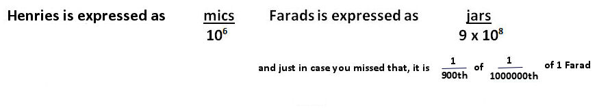
Note the airship's wavelength is expressed as "590 LS". The resonance of a tuned circuit (L and C) is said to be its 'LS' meaning CONSTANT RESONANCE where 'L' is in Henries and 'S' is in Farads.
|
- - - - - - - - - - - - - - - - |
The contents of this file 1910/4 are listed below. |
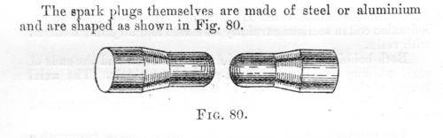
| p>Experiments to obtain a more selective receiver circuit - no time this year but ideas have been collected. Mediterranean and in the tropics - suffer from severe atmospherics. HMS Exmouth earmarked for trials but hampered by her refit - only 14 days trials in 3 months. Accurate tuning of receiving equipment (tuner/rejector/acceptor) seems to aid and increase the effects of atmospherics. Use of aperiodic's reduced equally the signal and the interference. Small independent receiving aerial placed very near to the main aerial (used on a send/receive switch) seems to pick up signals re-radiated from the main aerial. 'Traps' required in the main aerial build. Large majority of signals received on the main aerial are being wasted. A storage system is needed to store aerial energy not used by the receiver. HMS Exmouth's third report - suggests that all methods to combat the severe atmospherics in the Mediterranean and in the tropics have proved useless. HMS Vernon does not fully agree and suggests a way will be found with theoretical studies. Buzzer transmitter. Widely fitted in the Fleets and successful with a few minor modifications designed to increase range and note. Still in the 20 to 30 mile range. New pattern Morse key - designed so as to avoid the sparking/arcing experienced on the current key. This one has silver contacts and the fixed lower contact is now mounted on a spring lever, so instead of the key-bar banging the contact it now rubs against it. Again, the key sits inside a metal box with a hinged lid and the lead-cased cables are connected directly to it. The box is there to protect the operator from severe electrical shocks (especially in DC ships) and to protect the receivers detector from any sparks/arcs (shouldn't be any of course) which might occur. However, you will have to wait until you reach file Click Here to see the key although I don't think anybody will complain if you have a quick peep now. It has but one operators key and not the two of the key it takes over from and note that springy bottom contact. Improvements to Tuning Clips. Improved form of aerial feeder. In ships a 40-wire feeder will branch into 2 x 20-wire feeders somewhere up aloft ! Earth rings and earth wires. Porcelain Insulators in use with W/T apparatus - W/T installations will increase in efficiency when all the lignum vitæ insulators have been replaced by porcelain. Quick method of tuning transmitter apparatus. Big step forward! Type numbers introduced for W/T installations. Type 1 = Mk11. Type 2 = Mk1* Type 3 = Short Distance Set Type 4 = Destroyer Set. Type 5 = Portables Type 6 = Harbour Defence Set Type 7 = Horsea/Cleethorpes/Gibraltar Type 8 = Malta. Trials carried out in HMS Exmouth for spark plugs of a new design - the air blast (high speed revolving disk with newly designed plugs) blows out any arc formed. Not recommended because of possible electrical damage being caused by new plugs. Further trials conducted led the trials team to say "in all cases the special plugs had given distinctly better results than the Service pattern plug." The more the arcing could be reduced (or eliminated) the greater the range in distance achieved. Paragraphs 13 and 14 point out that HMS Vernon does not have the time or resources to address the problems of these new spark gap plugs. HMS Vernon is devoting time and resources to work on the quenched spark system with an intention of having it at sea in new ships. They said in response to HMS Exmouth report " When a completely satisfactory quenched spark set is arrived at, it is probably that the increased range required will be obtainable without such tensions in the aerial." It is now nearly 15 years since the spark transmitter was first used in the Royal Navy. A great number of experiments have been carried out on the basic understanding of spark technology, manifest in a shopping basket of a. AC current - ships DC supplies/rotaries/motor alternators. b. Lots of volts required - power transformers, VA = W but of course kW required. c. High speeds - to achieve high notes up to the 500 c/s mark. d. Charging and discharging of condenser across a physical adjustable gap - open type/quenched type, or rotary type with spark plugs, two gaps, and spinning disk (into which the spark plugs fitted) in synchrony with the alternators frequency. e. Spark oscillations - transformer where the secondary only transmits. f. Aerial and aerial induction. but still some way to go before a system which the Service is fully satisfied with, is introduced. |
- - - - - - - - - - - - - - - - |
The contents of this file 1910/5 are listed below. |
| Ventilation of W/T Offices and Silent Cabinets. No air conditioning (!) and note the need to supply larger circulation for ships in hot weather. I served in submarines in Singapore waters in the mid 1960's with what was laughingly called air conditioning stand alone units, when everything would be switched off for hours on end while we listened with our Type 186 (sonar set) for signals which rarely ever came - prickly heat is a killer in that it could drive one mad !
W/T trials between HMS Vernon and HMS Furious. Experiments to obtain a higher musical Morse tone with Mk11 sets (Type 1). Looking for a 700c/s note to make it easier to read through atmospherics.
All kind of reconfigurations of circuitry. Yet another new spark gap plug tried. Trials of improved revolving spark gap as recommended by HMS Suffolk in Mk1* installation (Type 2). Using this system a normal Service note (100 c/s) is obtained when running the motor at very low speeds, and if desired, very high notes without excessive motor speeds.
Experiments with quenched spark gap sets. Two sets used, called large - 3 spark gaps in series with key held down (longs) power taken = 5 to 6 kW and for normal Morse operating 3.5 to 4kW, and small - 2 spark gaps in series with key down taking 3kW and normal operating taking 2kW. Trial not successful and new spark gap is required. HMS Vernon said " the set is too unreliable with the present gaps to warrant introduction into the Service, but the results are so promising that trials will continue, and it is hoped a satisfactory spark gap will be arrived at shortly."
Date/Distance achieved/Strength of signal at receiver are shown but they assume that the gaps are behaving and working properly!
Airship spark set - the gap tends to arc as well as spark and a blower is required to blow out the arc. Blower is too heavy and could itself cause a fatal spark. Back to the drawing board. Hoping to develop the small transmitter used in the trial for the airship's use.
Receiving detectors. Type 'B' receiver performing well. More detectors being tried. Best detectors now stated as being (a) crystalite (b) carborundum-smalltite (c) bornite-zincite and (c) appears better than the current Service crystalite.
Brown's Relay. Very promising results though it is not yet ready for Service use.
Comparative trials of Leyden jars, Schultz condensers, Moschicki condensers. All three performed well but the Schultz was the best. No decision taken. Can the Schultz be made in the UK and how much would it cost?
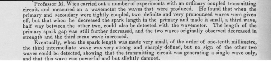
Quenched spark system of W/T. Before we start on this subject, let us see why all the excitement about the technique of quenching.
|
- - - - - - - - - - - - - - - - |
The contents of this file 1910/6 are listed below. |
| Report of Lieutenant Slee on the proposed W/T station at Fremantle Western Australia. NAUEN is at Brandenburg in Berlin. German design using a quenched spark transmitter and a Slaby-Arco set - transmission and receiver. Sparking condenser to charge to 30000 volts. Diagram of the transmitter/receiver circuits of Fremantle. - notice the spark gap configuration 30'odd in series.
The Poulsen sets are not a success on account of trouble in keeping the arc steady.
Report on Clifden and Poldhu.
Clifden - note comment on the earth and directions or reception and transmission, but that the earth serves both purposes.
Note the battery power - 16000 volts resulting in a current at the gap of 17 amps (serious stuff!). Speed of Morse keying is 18wpm but up to 60wpm gives satisfactory results. Output frequency is 19650 feet (50kHz/LS 9099.25). There is an oscillator capable of 24000 feet (40.9 kHz/LS 13572.25). Note their observation that the longer the wavelength the less likely the fading and interference given a finite distance - we of course know why - they didn't. Use of Valves for their receivers. No progress with duplex working. Talk about a "small power sparkless system" but such a set not seen or fitted. Average traffic at the station is 15000 word per week but 6000 per day could be coped with. Coltano is near Pisa, Tuscany, Italy on the coast of the Ligurian Sea.
Poldhu - No reception facilities. Transmits on a wavelength of 9000 (121kHz). Only operates between 0100 and 0300 daily when it sends its press and ship traffic twice at 15 wpm. Range is about 1900 miles. Station running well with no experiments being conducted. Cape Cod does the same work as Poldhu but is much less powerful.
Spark Photography at high power station Cleethorpes.
A major breakthrough in W/T technology and understanding. Wonderful detail of high speed photography with special effects. This was going on 17 years before the first commercially successful talking movie (The Jazz Singer) was screened. The results are not easy to take in and possibly much too technical for a Museum web site. However, if you do bother to look at this section, what follows may steer you in the right direction Spark Photography.
Diagram of a Motor Buzzer.
HMS Dreadnought's motor buzzer - range 20 miles and interception out to 40 miles and all this without a spark gap. Saving wear and tear on main W/T installation (set itself, alternator, spark gear, condenser, etc etc). HMS Vernon comments that whilst it is impressive HMS Vernon has no time to experiment and anyway, the present Service buzzer transmitter does its job properly. Mr Marconi first thought of this - what might he say when told a naval officer had developed his original idea ?
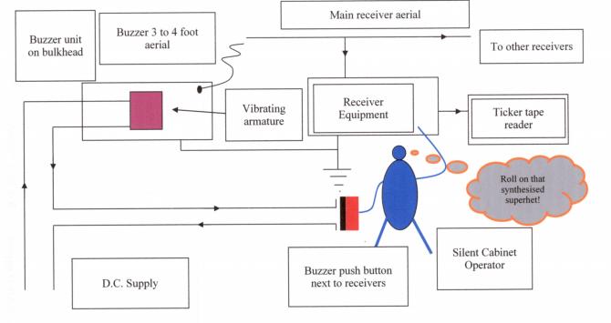
The buzzer transmitter - regularly mentioned but what is it?
You will readily recognise it in two ways, first of which is arriving at the front door of a house and pressing the buzzer. The buzzer is connected to an audio device which sounds an alarm (or signal) to which a response is required. Most of these buzzers will be connected via a battery - a DC system - but if not, via the mains which will transform the house mains voltage down to a low level of AC and then rectify it to change it to a low level of DC. Imagine what you would think if the caller started to send Morse code on your buzzer system! Now, safely inside the house, you switch on the lights and there is a click heard on the radio. This click comes from a tiny electrical spark within the switch which emits energy and specifically radio energy. If that energy could be maintained (God forbid) your light switches would turn into buzzers. The front door bell emits tiny amounts of radio energy all the time it is pressed and a suitable receiver would pick this up as a signal (not interference). That is exactly what the Royal Navy buzzer transmitter started out as. Let us have a look at a block diagram of the early system.
|
- - - - - - - - - - - - - - - - |
The contents of this file 1910/7 are listed below. |
| Report on experiments in directional telegraphy. HM Ships Prince of Wales and London. Directionality under Service conditions. Criteria of the trials using 'W' Tune (151kHz). HMS Vernon's report is very interesting especially when considering that war wasn't far away and that for the most part the Germans were actually blockaded in their own Ports.
Atmospheric conditions of the East Indies Station. Monsoon chasing! Southwest monsoon May to October - results on reception when the air is damp and there is lots of rain. 100 miles range only. Worst period May to end of July. HMS Terrible gave her position to HMS Hyacinth at 1135 miles range but Hyacinth could not answer. Musical note helps a great deal in bad conditions. Northeast monsoon October to May - conditions good in this period with extended ranges. Conditions at Colombo. Signal station required at Dondra Head which on the most southerly tip of Ceylon.
New patents describing inventions previously brought out and used in HM Navy. The Navy were using special earths in the trunking of ships from earlier that Mr Fessenden had claimed for his patent. Mr Marconi also claimed a patent for an earth used ashore in shore W/T stations but by the day he lodged his claim the navy had long been using this earth at Aberdeen, Ipswich, Pembroke, Horsea, Cleethorpes and Gibraltar.
Information on foreign ships and stations - intercepted by RN W/T stations.
|
- - - - - - - - - - - - - - - - |
The contents of this file 1910/8 are listed below. |
This directive supplanted the colour scheme which had been in being since the earliest days of electricity. Note the colours for W/T.
1910 Electrical Circuit Colours. |